Guides for SE student projects »
Using PlantUML
PlantUML is a tool for specifying various diagrams in a textual form. It is particularly useful in software projects where you want to update the diagrams incrementally, as the project evolves over time.
IDE Integrations
Some IDEs provide PlantUML plugins that you can use to work with plantUML diagrams seamlessly inside the IDE. Given below are two examples:
Setting up PlantUML in IntelliJ IDEA
Go to
File>Settingsto access theSettingspage.Go to
Settings>Plugins>Marketplaceand install the pluginplantuml4idea.Then go to
Settings>Languages & Frameworks>PlantUMLor search for PlantUML. You can also use a specific version of PlantUML from the releases page.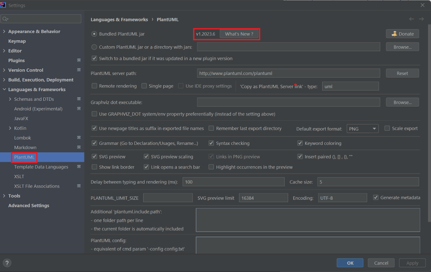
Working with PlantUML in IntelliJ IDEA
After installing the plantuml4idea plugin, simply create or open any .puml file to start editing it.
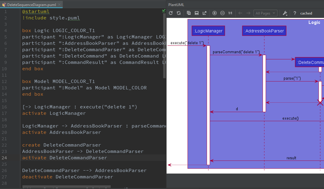
Any changes you make in editor pane on the left will be reflected in the preview pane on the right. However, do take note that these changes will not be reflected in your actual documentation until you export the diagram.
If the preview shows an error message about the dot executable not being found, you may need to install the Graphviz library manually.
Saving the Diagram as an image
- When using MarkBind as the site generation tool:
- MarkBind has built-in support for PlantUML. The diagram will be generated and saved as an image automatically. No additional work needed from you. Refer to [this section of the MarkBind User Guide](https://markbind.org/userGuide/components/i magesAndDiagrams.html#plantuml-diagrams) for more details.
- When using Jekyll as the site generation tool:
- The
plantuml4ideaplugin allows you to save individual diagrams to a location of your choosing. Click theSave Current Diagram Onlybutton and choose the location to export the image file. - You will have to
git addany new diagrams generated!
- The
Setting up PlantUML in VS Code
Go to
Extentions> SearchPlantUML> Install the PlantUML plugin by jebbs- Alternatively Launch VS Code Quick Open /
Ctrl+P|Cmd+P, paste the following command, and press enter:ext install plantuml
- Alternatively Launch VS Code Quick Open /
Install Graphviz (for best compatibility to render diagrams)
- Windows: download from Graphviz and add it to
PATH - MacOS:
brew install graphviz - Linux:
sudo apt install graphviz
- Windows: download from Graphviz and add it to
Configure PlantUML in VS Code
- Open VSCode Settings
- Search for "PlantUML"
- Set the path to
java(if not auto-detected):- Windows
plantuml.java: "C:\\Program Files\\Java\\jdk-11\\bin\\java.exe" - Linux/MacOS
plantuml.java: "/usr/bin/java"
- Windows
- (Optional) Set PlantUML Server (if not using local rendering):
Add plantuml.server: "https://www.plantuml.com/plantuml"
Working with PlantUML in VS Code
After installing the PlantUML integration plugin, simply create or open any .puml file to start editing it.
Any changes you make in editor pane on the left will be reflected in the preview pane on the right. However, do take note that these changes will not be reflected in your actual documentation until you export the diagram.
Saving the Diagram as an image
When using MarkBind as the site generation tool:
- MarkBind has built-in support for PlantUML. The diagram will be generated and saved as an image automatically. No additional work needed from you. Refer to this section of the MarkBind User Guide for more details.
When Using Other Tools (e.g. Jekyll, Static Site Generators, or Docs):
- Export Individual Diagrams:
- Open the PlantUML preview (/
Alt+D|option+Dor right-click → Preview Current Diagram) - Right-click the preview and select "Export Current Diagram"
- Choose the format (PNG/SVG/PDF) and save to your desired location (e.g.
/docs/images/).
- Open the PlantUML preview (/
- Export All Diagrams in a File:
- Use the Command Palette (/
Ctrl+Shift+P|Cmd+Shift+P) → PlantUML: Export All Diagrams.
- Use the Command Palette (/
- Git Tracking:
- Remember to
git addnewly exported image files if they’re part of your repo.
- Remember to
- Export Individual Diagrams:
Tips and tricks
Maintaining consistency in formatting
It is highly recommended to consistently color your UML diagrams as an visual aid. You can achieve this by creating a dictionary of colors and import it like CSS.
For example, you can create a Style.puml with the contents:
Style.puml.
!define LOGIC_COLOR #3333C4
!define LOGIC_COLOR_T1 #7777DB
!define LOGIC_COLOR_T2 #5252CE
!define LOGIC_COLOR_T3 #1616B0
!define LOGIC_COLOR_T4 #101086
Then you can use it in another PlantUML file like this:
UndoSequenceDiagram.puml.
!include Style.puml
box Logic LOGIC_COLOR_T2
participant ":LogicManager" as LogicManager LOGIC_COLOR
participant ":AddressBookParser" as AddressBookParser LOGIC_COLOR
participant ":UndoCommand" as UndoCommand LOGIC_COLOR
end box
You can fine-tune the formatting of PlantUML diagrams with the skinparam command. For example, skinparam backgroundColor transparent turns the background of the diagram transparent.
For a comprehensive list of skinparams, see unofficial PlantUML skinparam documentation.
Repositioning elements
While PlantUML’s automatic layout engine usually produces satisfactory results, at times the result can be less than ideal, especially on larger diagrams. Here is an example where the default layout generated by PlantUML has a lot of overlapping lines that are hard to decipher:
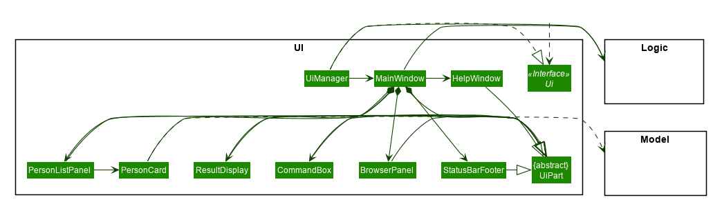
In most cases, you should consider decomposing the diagram into smaller ones or focusing on a more specific portion of the diagram.
Here are some techniques you can use to obtain a more palatable diagram.
Link lengths
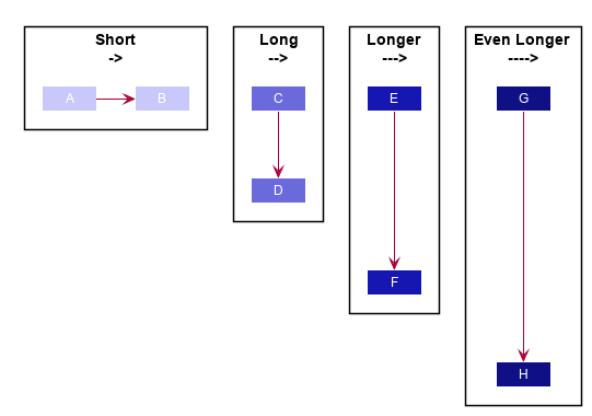
By default, a short link (->) points to right and a long link (-->) points downwards. you can extend any link to make it longer (--->).
Link directions
Clever usage of arrow directions will resolve most layout issues. For example, the table below shows how the way in which you specify arrows can results in drastically different layouts for the same diagram.
| Source | Result |
|---|---|
A --> Z B --> Z C --> Z D --> Z | 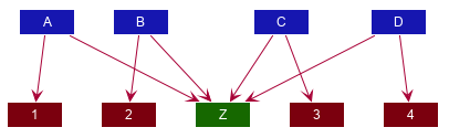 |
'default is down A --> Z 'specify down B -down-> Z 'shorthand for down C -d-> Z 'arrow lengths take priority D -down> Z A -up-> 1 B -up-> 2 C -up-> 3 D -up-> 4 | 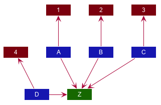 |
A -up-> Z B -up-> Z C -up-> Z D -up-> Z A --> 1 B --> 2 C --> 3 D --> 4 'Force A B C D A -right[hidden]- B B -right[hidden]- C C -right[hidden]- D | 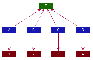 |
Another technique you can use to influence the layout is to reorder definitions. The layout engine will attempt to order objects in the order in which they are defined. If there is no formal definition, the objects is taken to be declared upon its first usage.
| Source | Result |
|---|---|
A --> B C --> D | 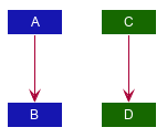 |
'Class C is defined before A Class C A --> B C --> D | 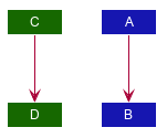 |
package "Rule Of Thumb";{
    Class C
    A --> B
    C --> D
}
| 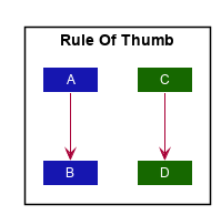 |
Explicitly define all symbols to avoid any potential layout mishaps.
Using reference frames
Reference frames in PlantUML sequence diagrams allow you to group and reuse sequences of interactions, which helps improve readability and reduce repetition in complex scenarios. By encapsulating sequences into reference frames, you can also reduce complexity, making it easier to manage and understand the overall flow of interactions within your diagrams.
Refer to the following example:
@startuml
hide footbox
skinparam sequenceReferenceBackgroundColor #f7807c
actor Player
participant ":TextUi" as TextUi #EE82EE
participant ":MSLogic" as MSLogic #90EE90
Player -> TextUi : mark x y
TextUi -> MSLogic : markCellAt(x, y)
return
TextUi -> MSLogic : getAppearanceOfCellAt(x, y)
MSLogic -> TextUi : getConfig()
TextUi --> MSLogic : config
MSLogic --> TextUi : cellAppearance
TextUi --> Player : Show updated minefield
@enduml

The sequence diagram illustrates two main actions: marking a cell and retrieving its appearance. We can simplify the diagram by moving the latter into a new reference frame.
First we update the original diagram as follows:
@startuml
hide footbox
skinparam sequenceReferenceBackgroundColor #f7807c
actor Player
participant ":TextUi" as TextUi #EE82EE
participant ":MSLogic" as MSLogic #90EE90
Player -> TextUi : mark x y
TextUi -> MSLogic : markCellAt(x, y)
return
ref over TextUi, MSLogic
get minefield appearance
end ref
TextUi --> Player : Show updated minefield
@enduml

Then, we create a new diagram for the reference frame.
@startuml
hide footbox
participant ":TextUi" as TextUi #EE82EE
participant ":MSLogic" as MSLogic #90EE90
group sd get minefield appearance
TextUi -> MSLogic : getAppearanceOfCellAt(x, y)
MSLogic -> TextUi : getConfig()
TextUi --> MSLogic : config
MSLogic --> TextUi : cellAppearance
end
@enduml

Authors:
- Initial Version: Jeffry Lum
- Contributors:
- MUHAMMAD FIKRI BIN ABDUL KALAM (@mfjkri): added the part on SD reference frames