BOOK: SOFTWARE ENGINEERING FOR SELF-DIRECTED LEARNERS
SECTION: INTRODUCTION
Software Engineering
Introduction
The following description of the Joys of the Programming Craft was taken (and emphasis added) from Chapter 1 of the famous book The Mythical Man-Month, by Frederick P. Brooks.
Why is programming fun? What delights may its practitioner expect as his reward?
First is the sheer joy of making things. As the child delights in his mud pie, so the adult enjoys building things, especially things of his own design. I think this delight must be an image of God's delight in making things, a delight shown in the distinctness and newness of each leaf and each snowflake.
Second is the pleasure of making things that are useful to other people. Deep within, you want others to use your work and to find it helpful. In this respect the programming system is not essentially different from the child's first clay pencil holder "for Daddy's office."
Third is the fascination of fashioning complex puzzle-like objects of interlocking moving parts and watching them work in subtle cycles, playing out the consequences of principles built in from the beginning. The programmed computer has all the fascination of the pinball machine or the jukebox mechanism, carried to the ultimate.
Fourth is the joy of always learning, which springs from the nonrepeating nature of the task. In one way or another the problem is ever new, and its solver learns something: sometimes practical, sometimes theoretical, and sometimes both.
Finally, there is the delight of working in such a tractable medium. The programmer, like the poet, works only slightly removed from pure thought-stuff. He builds his castles in the air, from air, creating by the exertion of the imagination. Few media of creation are so flexible, so easy to polish and rework, so readily capable of realizing grand conceptual structures....
Yet the program construct, unlike the poet's words, is real in the sense that it moves and works, producing visible outputs separate from the construct itself. It prints results, draws pictures, produces sounds, moves arms. The magic of myth and legend has come true in our time. One types the correct incantation on a keyboard, and a display screen comes to life, showing things that never were nor could be.
Programming then is fun because it gratifies creative longings built deep within us and delights sensibilities you have in common with all men.
Not all is delight, however, and knowing the inherent woes makes it easier to bear them when they appear.
First, one must perform perfectly. The computer resembles the magic of legend in this respect, too. If one character, one pause, of the incantation is not strictly in proper form, the magic doesn't work. Human beings are not accustomed to being perfect, and few areas of human activity demand it. Adjusting to the requirement for perfection is, I think, the most difficult part of learning to program.
Next, other people set one's objectives, provide one's resources, and furnish one's information. One rarely controls the circumstances of his work, or even its goal. In management terms, one's authority is not sufficient for his responsibility. It seems that in all fields, however, the jobs where things get done never have formal authority commensurate with responsibility. In practice, actual (as opposed to formal) authority is acquired from the very momentum of accomplishment.
The dependence upon others has a particular case that is especially painful for the system programmer. He depends upon other people's programs. These are often maldesigned, poorly implemented, incompletely delivered (no source code or test cases), and poorly documented. So he must spend hours studying and fixing things that in an ideal world would be complete, available, and usable.
The next woe is that designing grand concepts is fun; finding nitty little bugs is just work. With any creative activity come dreary hours of tedious, painstaking labor, and programming is no exception.
Next, one finds that debugging has a linear convergence, or worse, where one somehow expects a quadratic sort of approach to the end. So testing drags on and on, the last difficult bugs taking more time to find than the first.
The last woe, and sometimes the last straw, is that the product over which one has labored so long appears to be obsolete upon (or before) completion. Already colleagues and competitors are in hot pursuit of new and better ideas. Already the displacement of one's thought-child is not only conceived, but scheduled.
This always seems worse than it really is. The new and better product is generally not available when one completes his own; it is only talked about. It, too, will require months of development. The real tiger is never a match for the paper one, unless actual use is wanted. Then the virtues of reality have a satisfaction all their own.
Of course the technological base on which one builds is always advancing. As soon as one freezes a design, it becomes obsolete in terms of its concepts. But implementation of real products demands phasing and quantizing. The obsolescence of an implementation must be measured against other existing implementations, not against unrealized concepts. The challenge and the mission are to find real solutions to real problems on actual schedules with available resources.
This then is programming, both a tar pit in which many efforts have floundered and a creative activity with joys and woes all its own. For many, the joys far outweigh the woes....
SECTION: PROGRAMMING PARADIGMS
Object-Oriented Programming
Introduction
Object-Oriented Programming (OOP) is a programming paradigm. A programming paradigm guides programmers to analyze programming problems, and structure programming solutions, in a specific way.
Programming languages have traditionally divided the world into two parts—data and operations on data. Data is static and immutable, except as the operations may change it. The procedures and functions that operate on data have no lasting state of their own; they’re useful only in their ability to affect data.
This division is, of course, grounded in the way computers work, so it’s not one that you can easily ignore or push aside. Like the equally pervasive distinctions between matter and energy and between nouns and verbs, it forms the background against which you work. At some point, all programmers—even object-oriented programmers—must lay out the data structures that their programs will use and define the functions that will act on the data.
With a procedural programming language like C, that’s about all there is to it. The language may offer various kinds of support for organizing data and functions, but it won’t divide the world any differently. Functions and data structures are the basic elements of design.
Object-oriented programming doesn’t so much dispute this view of the world as restructure it at a higher level. It groups operations and data into modular units called objects and lets you combine objects into structured networks to form a complete program. In an object-oriented programming language, objects and object interactions are the basic elements of design.
Some other examples of programming paradigms are:
| Paradigm | Programming Languages |
|---|---|
| Procedural Programming paradigm | C |
| Functional Programming paradigm | F#, Haskell, Scala |
| Logic Programming paradigm | Prolog |
Some programming languages support multiple paradigms.
Java is primarily an OOP language but it supports limited forms of functional programming and it can be used to (although not recommended to) write procedural code. e.g., se-edu/addressbook-level1
JavaScript and Python support functional, procedural, and OOP programming.
Objects
An object in Object-Oriented Programming (OOP) has state and behavior, similar to objects in the real world.
Every object has both state (data) and behavior (operations on data). In that, they’re not much different from ordinary physical objects. It’s easy to see how a mechanical device, such as a pocket watch or a piano, embodies both state and behavior. But almost anything that’s designed to do a job does, too. Even simple things with no moving parts such as an ordinary bottle combine state (how full the bottle is, whether or not it’s open, how warm its contents are) with behavior (the ability to dispense its contents at various flow rates, to be opened or closed, to withstand high or low temperatures).
It’s this resemblance to real things that gives objects much of their power and appeal. They can not only model components of real systems, but equally as well fulfill assigned roles as components in software systems.
OOP views the world as a network of interacting objects.
A real world scenario viewed as a network of interacting objects:
You are asked to find out the average age of a group of people Adam, Beth, Charlie, and Daisy. You take a piece of paper and pen, go to each person, ask for their age, and note it down. After collecting the age of all four, you enter it into a calculator to find the total. And then, use the same calculator to divide the total by four, to get the average age. This can be viewed as the objects You, Pen, Paper, Calculator, Adam, Beth, Charlie, and Daisy interacting to accomplish the end result of calculating the average age of the four persons. These objects can be considered as connected in a certain network of certain structure that dictates how these objects can interact. For example, You object is connected to the Pen object, and hence You can use the Pen object to write.
OOP solutions try to create a similar object network inside the computer’s memory – a sort of virtual simulation of the corresponding real world scenario – so that a similar result can be achieved programmatically.
OOP does not demand that the virtual world object network follow the real world exactly.
Our previous example can be tweaked a bit as follows:
- Use an object called
Mainto represent your role in the scenario. - As there is no physical writing involved, you can replace the
PenandPaperwith an object calledAgeListthat is able to keep a list of ages.
Every object has both state (data) and behavior (operations on data).
The state and behavior of our running example are as follows:
| Object | Real World? | Virtual World? | Example of State (i.e., Data) | Examples of Behavior (i.e., Operations) |
|---|---|---|---|---|
| Adam | Name, Date of Birth | Calculate age based on birthday | ||
| Pen | - | Ink color, Amount of ink remaining | Write | |
| AgeList | - | Recorded ages | Give the number of entries, Accept an entry to record | |
| Calculator | Numbers already entered | Calculate the sum, divide | ||
| You/Main | Average age, Sum of ages | Use other objects to calculate |
Every object has an interface and an implementation.
Every real world object has,
- an interface through which other objects can interact with it, and,
- an implementation that supports the interface but may not be accessible to the other object.
The interface and implementation of some real-world objects in our example:
- Calculator: the buttons and the display are part of the interface; circuits are part of the implementation.
- Adam: In the context of our 'calculate average age' example,
- the interface of Adam consists of requests that Adam will respond to, e.g., "Give age to the nearest year, as at Jan 1st of this year" "State your name".
- the implementation includes the mental calculation Adam uses to calculate the age which is not visible to other objects.
Similarly, every object in the virtual world has an interface and an implementation.
The interface and implementation of some virtual-world objects in our example:
Adam: the interface might have a methodgetAge(Date asAt); the implementation of that method is not visible to other objects.
Objects interact by sending messages. Both real world and virtual world object interactions can be viewed as objects sending messages to each other. The message can result in the sender object receiving a response and/or the receiver object’s state being changed. Furthermore, the result can vary based on which object received the message, even if the message is identical (see rows 1 and 2 in the example below).
Same messages and responses from our running example:
| World | Sender | Receiver | Message | Response | State Change |
|---|---|---|---|---|---|
| Real | You | Adam | "What is your name?" | "Adam" | - |
| Real | as above | Beth | as above | "Beth" | - |
| Real | You | Pen | Put nib on paper and apply pressure | Makes a mark on your paper | Ink level goes down |
| Virtual | Main | Calculator (current total is 50) | add(int i): int i = 23 | 73 | total = total + 23 |
The concept of Objects in OOP is an abstraction mechanism because it allows us to abstract away the lower level details and work with bigger granularity entities i.e., ignore details of data formats and the method implementation details and work at the level of objects.
You can deal with a Person object that represents the person Adam and query the object for Adam's age instead of dealing with details such as Adam’s date of birth (DoB), in what format the DoB is stored, the algorithm used to calculate the age from the DoB, etc.
Encapsulation protects an implementation from unintended actions and from inadvertent access.
-- Object-Oriented Programming with Objective-C, Apple
An object is an encapsulation of some data and related behavior in terms of two aspects:
1. The packaging aspect: An object packages data and related behavior together into one self-contained unit.
2. The information hiding aspect: The data in an object is hidden from the outside world and are only accessible using the object's interface.
Classes
Writing an OOP program is essentially writing instructions that the computer will use to,
- create the virtual world of the object network, and
- provide it the inputs to produce the outcome you want.
A class contains instructions for creating a specific kind of objects. It turns out sometimes multiple objects keep the same type of data and have the same behavior because they are of the same kind. Instructions for creating a 'kind' (or ‘class’) of objects can be done once and those same instructions can be used to objects of that kind. We call such instructions a Class.
Classes and objects in an example scenario
Consider the example of writing an OOP program to calculate the average age of Adam, Beth, Charlie, and Daisy.
Instructions for creating objects Adam, Beth, Charlie, and Daisy will be very similar because they are all of the same kind: they all represent ‘persons’ with the same interface, the same kind of data (i.e., name, dateOfBirth, etc.), and the same kind of behavior (i.e., getAge(Date), getName(), etc.). Therefore, you can have a class called Person containing instructions on how to create Person objects and use that class to instantiate objects Adam, Beth, Charlie, and Daisy.
Similarly, you need classes AgeList, Calculator, and Main classes to instantiate one each of AgeList, Calculator, and Main objects.
| Class | Objects |
|---|---|
Person | objects representing Adam, Beth, Charlie, Daisy |
AgeList | an object to represent the age list |
Calculator | an object to do the calculations |
Main | an object to represent you (i.e., the one who manages the whole operation) |
While all objects of a class have the same attributes, each object has its own copy of the attribute value.
All Person objects have the name attribute but the value of that attribute varies between Person objects.
However, some attributes are not suitable to be maintained by individual objects. Instead, they should be maintained centrally, shared by all objects of the class. They are like ‘global variables’ but attached to a specific class. Such variables whose value is shared by all instances of a class are called class-level attributes.
The attribute totalPersons should be maintained centrally and shared by all Person objects rather than copied at each Person object.
Similarly, when a normal method is being called, a message is being sent to the receiving object and the result may depend on the receiving object.
Sending the getName() message to the Adam object results in the response "Adam" while sending the same message to the Beth object results in the response "Beth".
However, there can be methods related to a specific class but not suitable for sending messages to a specific object of that class. Such methods that are called using the class instead of a specific instance are called class-level methods.
The method getTotalPersons() is not suitable to send to a specific Person object because a specific object of the Person class should not have to know about the total number of Person objects.
Class-level attributes and methods are collectively called class-level members (also called static members sometimes because some programming languages use the keyword static to identify class-level members). They are to be accessed using the class name rather than an instance of the class.
An Enumeration is a fixed set of values that can be considered as a data type. An enumeration is often useful when using a regular data type such as int or String would allow invalid values to be assigned to a variable.
Suppose you want a variable called priority to store the priority of something. There are only three priority levels: high, medium, and low. You can declare the variable priority as of type int and use only values 2, 1, and 0 to indicate the three priority levels. However, this opens the possibility of an invalid value such as 9 being assigned to it. But if you define an enumeration type called Priority that has three values HIGH, MEDIUM and LOW only, a variable of type Priority will never be assigned an invalid value because the compiler is able to catch such an error.
Priority: HIGH, MEDIUM, LOW
Associations
Objects in an OO solution need to be connected to each other to form a network so that they can interact with each other. Such connections between objects are called associations.
Suppose an OOP program for managing a learning management system creates an object structure to represent the related objects. In that object structure you can expect to have associations between a Course object that represents a specific course and Student objects that represent students taking that course.
Associations in an object structure can change over time.
To continue the previous example, the associations between a Course object and Student objects can change as students enroll in the course or drop the course over time.
Associations among objects can be generalized as associations between the corresponding classes too.
In our example, as some Course objects can have associations with some Student objects, you can view it as an association between the Course class and the Student class.
Implementing associations
You use instance level variables to implement associations.
In our example, the Course class can have a students variable to keeps track of students associated with a particular course.
When two classes are linked by an association, it does not necessarily mean both objects taking part in an instance of the association knows about (i.e., has a reference to) each other. The concept of navigability tells us if an object taking part in association knows about the other. In other words, it tells us if we can 'navigate' from the one object to the other in a given direction -- because if the object 'knows' about the other, it has a reference to the other object, and we can use that reference to 'navigate to' (i.e., access) that other object.
Navigability can be unidirectional or bidirectional. Suppose there is an association between the classes Box and Rope, and the Box object b and the Rope object r is taking part in one instance of that association.
- Unidirectional: If the navigability is from
BoxtoRope,bwill have a reference torbutrwill not have a reference tob. That is, one can navigate frombtorusing theb's object reference ofr(but not in the other direction).
Similarly, if the navigability is in the other direction,rwill have a reference tobbutbwill not have a reference tor. - Bidirectional:
bwill have a reference torandrwill have a reference tobi.e., the two objects will be pointing to each other for the same single instance of the association.
Note that two unidirectional associations in opposite directions do not add up to a single bidirectional association.
In the code below, there is a bidirectional association between the Person class and the Cat class i.e., if Person p is the owner of the Cat c, p it will result in p and c having references to each other.
class Person {
    Cat pet;
    //...
}

class Cat{
    Person owner;
    //...
}
class Person:

  def __init__(self):
    self.pet = None  # a Cat object


class Cat:

  def __init__(self):
    self.owner = None  # a Person object
The code below has two unidirectional associations between the Person class and the Cat class (in opposite directions). Because the breeder is not necessarily the same person keeping the cat as a pet, they are two separate associations, not a bidirectional association.
class Person {
    Cat pet;
    //...
}

class Cat{
    Person breeder;
    //...
}
class Person:

  def __init__(self):
    self.pet = None  # a Cat object


class Cat:

  def __init__(self):
    self.breeder = None  # a Person object
Multiplicity is the aspect of an OOP solution that dictates how many objects take part in each association.
The multiplicity of the association between Course objects and Student objects tells you how many Course objects can be associated with one Student object and vice versa.
Implementing multiplicity
A normal instance-level variable gives us a 0..1 multiplicity (also called optional associations) because a variable can hold a reference to a single object or null.
In the code below, the Logic class has a variable that can hold 0..1 i.e., zero or one Minefield objects.
class Logic {
    Minefield minefield;
    // ...
}

class Minefield {
    //...
}
class Logic:

  def __init__(self):
    self.minefield = None

  # ...


class Minefield:
  # ...
A variable can be used to implement a 1 multiplicity too (also called compulsory associations).
In the code below, the Logic class will always have a ConfigGenerator object, provided the variable is not set to null at some point.
class Logic {
    ConfigGenerator cg = new ConfigGenerator();
    ...
}
In the Logic class, ensure there is a variable that refers to a ConfigGenerator object.
To implement other multiplicities, choose a suitable data structure such as Arrays, ArrayLists, HashMaps, Sets, etc.
This code uses a two-dimensional array to implement a 1-to-many association from the Minefield to Cell.
class Minefield {
    Cell[][] cell;
    //...
}
class Minefield:

  def __init__(self):
    self.cells = {1:[], 2:[], 3:[]}
In the context of OOP associations, a dependency is a need for one class to depend on another without having a direct association in the same direction. Reason for the exclusion: If there is an association from class Foo to class Bar (i.e., navigable from Foo to Bar), that means Foo is obviously dependent on Bar and hence there is no point in mentioning dependency specifically. In other words, we are specifically focusing on non-obvious dependencies here. One cause of such dependencies is interactions between objects that do not have a long-term link between them.
A Course class can have a dependency on a Registrar class because the Course class needs to refer to the Registrar class to obtain the maximum number of students it can support (e.g., Registrar.MAX_COURSE_CAPACITY).
In the code below, Foo has a dependency on Bar but it is not an association because it is only a interaction and there is no long term relationship between a Foo object and a Bar object. i.e., the Foo object does not keep the Bar object it receives as a parameter.
class Foo {

    int calculate(Bar bar) {
        return bar.getValue();
    }
}

class Bar {
    int value;

    int getValue() {
        return value;
    }
}
class Foo:

    def calculate(self, bar):
        return bar.value;

class Bar:

    def __init__(self, value):
      self.value = value
A composition is an association that represents a strong whole-part relationship.
A Board (used for playing board games) consists of Square objects.
Composition implies,
- when the whole is destroyed, parts are destroyed too i.e., the part cannot exist without being attached to a whole.
- there cannot be cyclical links.
The ‘sub-folder’ association between Folder objects is a composition type association. Consider the case of Folder object subF is a sub-folder of Folder object F. In this case,
- if
Fis deleted,subFwill be deleted with it. Fcannot be a sub-folder ofsubF(i.e., no cyclical 'sub-folder' association between the two objects).
Whether a relationship is a composition can depend on the context.
Is the relationship between Email and EmailSubject composition? That is, is the email subject part of an email to the extent that an email subject cannot exist without an email?
- When modeling an application that sends emails, the answer is 'yes'.
- When modeling an application that gather analytics about email traffic, the answer may be 'no' (e.g., the application might collect just the email subjects for text analysis).
A common use of composition is when parts of a big class are carved out as smaller classes for the ease of managing the internal design. In such cases, the classes extracted out still act as parts of the bigger class and the outside world has no business knowing about them.
Cascading deletion alone is not sufficient for composition. Suppose there is a design in which Person objects are attached to Task objects and the former get deleted whenever the latter is deleted. This fact alone does not mean there is a composition relationship between the two classes. For it to be composition, a Person must be an integral part of a Task in the context of that association, at the concept level (not simply at implementation level).
Identifying and keeping track of composition relationships in the design has benefits such as helping to maintain the data integrity of the system. For example, when you know that a certain relationship is a composition, you can take extra care in your implementation to ensure that when the whole object is deleted, all its parts are deleted too.
Implementing composition
Composition is implemented using a normal variable. If correctly implemented, the ‘part’ object will be deleted when the ‘whole’ object is deleted. Ideally, the ‘part’ object may not even be visible to clients of the ‘whole’ object.
Here is one way to implement the composition between Email and Subject:
class Email {
    private Subject subject;
  ...
}
class Email:

  def __init__(self):
    self.__subject = Subject()
In this code, the Email has a composition type relationship with the Subject class, in the sense that the subject is part of the email.
Aggregation represents a container-contained relationship. It is a weaker relationship than composition.
SportsClub can act as a container for Person objects who are members of the club. Person objects can survive without a SportsClub object.
Implementing aggregation
Implementation is similar to that of composition except the containee object can exist even after the container object is deleted.
In the code below, there is an aggregation association between the Team class and the Person class in that a Team contains a Person object who is the leader of the team.
class Team {
    Person leader;
    ...
    void setLeader(Person p) {
        leader = p;
    }
}
class Team:

  def __init__(self):
    self.__leader = None

  def set_leader(self, person):
    self.__leader = person
An association class represents additional information about an association. It is a normal class but plays a special role from a design point of view.
A Man class and a Woman class are linked with a ‘married to’ association and there is a need to store the date of marriage. However, that data is related to the association rather than specifically owned by either the Man object or the Woman object. In such situations, an additional association class can be introduced, e.g., a Marriage class, to store such information.
Implementing association classes
There is no special way to implement an association class. It can be implemented as a normal class that has variables to represent the endpoint of the association it represents.
In the code below, the Transaction class is an association class that represents a transaction between a Person who is the seller and another Person who is the buyer.
class Transaction {

    //all fields are compulsory
    Person seller;
    Person buyer;
    Date date;
    String receiptNumber;

    Transaction(Person seller, Person buyer, Date date, String receiptNumber) {
        //set fields
    }
}
Inheritance
The OOP concept Inheritance allows you to define a new class based on an existing class.
For example, you can use inheritance to define an EvaluationReport class based on an existing Report class so that the EvaluationReport class does not have to duplicate data/behaviors that are already implemented in the Report class. The EvaluationReport can inherit the wordCount attribute and the print() method from the base class Report.
- Other names for Base class: Parent class, Superclass
- Other names for Derived class: Child class, Subclass, Extended class
A superclass is said to be more general than the subclass. Conversely, a subclass is said to be more specialized than the superclass.
Applying inheritance on a group of similar classes can result in the common parts among classes being extracted into more general classes.
Man and Woman behave the same way for certain things. However, the two classes cannot be simply replaced with a more general class Person because of the need to distinguish between Man and Woman for certain other things. A solution is to add the Person class as a superclass (to contain the code common to men and women) and let Man and Woman inherit from Person class.
Inheritance implies the derived class can be considered as a subtype of the base class (and the base class is a super-type of the derived class), resulting in an is a relationship.
Inheritance does not necessarily mean a subtype relationship exists. However, the two often go hand-in-hand. For simplicity, at this point let us assume inheritance implies a subtype relationship.
To continue the previous example,
Womanis aPersonManis aPerson
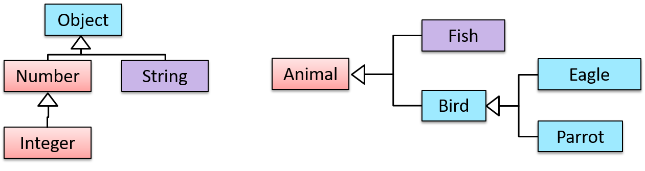
Inheritance relationships through a chain of classes can result in inheritance hierarchies (aka inheritance trees).
Two inheritance hierarchies/trees are given below. Note that the triangle points to the parent class. Observe how the Parrot is a Bird as well as it is an Animal.
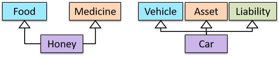
Multiple Inheritance is when a class inherits directly from multiple classes. Multiple inheritance among classes is allowed in some languages (e.g., Python, C++) but not in other languages (e.g., Java, C#).
The Honey class inherits from the Food class and the Medicine class because honey can be consumed as a food as well as a medicine (in some oriental medicine practices). Similarly, a Car is a Vehicle, an Asset and a Liability.
Method overriding is when a subclass changes the behavior inherited from the parent class by re-implementing the method. Overridden methods have the same name, the same type signature, and the same (or a subtype of the) return type.
Consider the following case of EvaluationReport class inheriting the Report class:
Report methods | EvaluationReport methods | Overrides? |
|---|---|---|
print() | print() | Yes |
write(String) | write(String) | Yes |
read():String | read(int):String | No. Reason: the two methods have different signatures; This is a case of overloading (rather than overriding). |
Method overloading is when there are multiple methods with the same name but different type signatures. Overloading is used to indicate that multiple operations do similar things but take different parameters.
Type signature: The type signature of an operation is the type sequence of the parameters. The return type and parameter names are not part of the type signature. However, the parameter order is significant.
Example:
| Method | Type Signature |
|---|---|
int add(int X, int Y) | (int, int) |
void add(int A, int B) | (int, int) |
void m(int X, double Y) | (int, double) |
void m(double X, int Y) | (double, int) |
In the case below, the calculate method is overloaded because the two methods have the same name but different type signatures (String) and (int).
calculate(String): voidcalculate(int): void
An interface is a behavior specification i.e., a collection of . If a class , it means the class is able to support the behaviors specified by the said interface.
There are a number of situations in software engineering when it is important for disparate groups of programmers to agree to a "contract" that spells out how their software interacts. Each group should be able to write their code without any knowledge of how the other group's code is written. Generally speaking, interfaces are such contracts. --Oracle Docs on Java
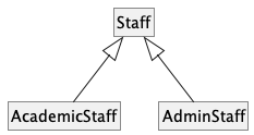
Suppose SalariedStaff is an interface that contains two methods setSalary(int) and getSalary(). AcademicStaff can declare itself as implementing the SalariedStaff interface, which means the AcademicStaff class must implement all the methods specified by the SalariedStaff interface i.e., setSalary(int) and getSalary().
A class implementing an interface results in an is-a relationship, just like in class inheritance.
In the example above, AcademicStaff is a SalariedStaff. An AcademicStaff object can be used anywhere a SalariedStaff object is expected e.g., SalariedStaff ss = new AcademicStaff().
Abstract class: A class declared as an abstract class cannot be instantiated, but it can be subclassed.
You can declare a class as abstract when a class is merely a representation of commonalities among its subclasses in which case it does not make sense to instantiate objects of that class.
The Animal class that exists as a generalization of its subclasses Cat, Dog, Horse, Tiger etc. can be declared as abstract because it does not make sense to instantiate an Animal object.
Abstract method: An abstract method is a method signature without a method implementation.
The move method of the Animal class is likely to be an abstract method as it is not possible to implement a move method at the Animal class level to fit all subclasses because each animal type can move in a different way.
A class that has an abstract method becomes an abstract class because the class definition is incomplete (due to the missing method body) and it is not possible to create objects using an incomplete class definition.
Dynamic binding (): a mechanism where method calls in code are at , rather than at compile time.
Overridden methods are resolved using dynamic binding, and therefore resolves to the implementation in the actual type of the object.
Consider the code below. The declared type of s is Staff and it appears as if the adjustSalary(int) operation of the Staff class is invoked.
void adjustSalary(int byPercent) {
    for (Staff s: staff) {
        s.adjustSalary(byPercent);
    }
}
However, at runtime s can receive an object of any subclass of Staff. That means the adjustSalary(int) operation of the actual subclass object will be called. If the subclass does not override that operation, the operation defined in the superclass (in this case, Staff class) will be called.
Static binding (aka early binding): When a method call is resolved at compile time.
In contrast, overloaded methods are resolved using static binding.
Note how the constructor is overloaded in the class below. The method call new Account() is bound to the first constructor at compile time.
class Account {

    Account() {
        // Signature: ()
        ...
    }

    Account(String name, String number, double balance) {
        // Signature: (String, String, double)
        ...
    }
}
Similarly, the calculateGrade method is overloaded in the code below and a method call calculateGrade("A1213232") is bound to the second implementation, at compile time.
void calculateGrade(int[] averages) { ... }
void calculateGrade(String matric) { ... }
Every instance of a subclass is an instance of the superclass, but not vice-versa. As a result, inheritance allows substitutability: the ability to substitute a child class object where a parent class object is expected.
An AcademicStaff is an instance of a Staff, but a Staff is not necessarily an instance of an AcademicStaff. i.e., wherever an object of the superclass is expected, it can be substituted by an object of any of its subclasses.
The following code is valid because an AcademicStaff object is substitutable as a Staff object.
Staff staff = new AcademicStaff(); // OK
But the following code is not valid because staff is declared as a Staff type and therefore its value may or may not be of type AcademicStaff, which is the type expected by variable academicStaff.
Staff staff;
...
AcademicStaff academicStaff = staff; // Not OK
Polymorphism
Polymorphism:
The ability of different objects to respond, each in its own way, to identical messages is called polymorphism. -- Object-Oriented Programming with Objective-C, Apple
Polymorphism allows you to write code targeting superclass objects, use that code on subclass objects, and achieve possibly different results based on the actual class of the object.
Assume classes Cat and Dog are both subclasses of the Animal class. You can write code targeting Animal objects and use that code on Cat and Dog objects, achieving possibly different results based on whether it is a Cat object or a Dog object. Some examples:
- Declare an array of type
Animaland still be able to storeDogandCatobjects in it. - Define a method that takes an
Animalobject as a parameter and yet be able to passDogandCatobjects to it. - Call a method on a
Dogor aCatobject as if it is anAnimalobject (i.e., without knowing whether it is aDogobject or aCatobject) and get a different response from it based on its actual class e.g., call theAnimalclass's methodspeak()on objectaand get a"Meow"as the return value ifais aCatobject and"Woof"if it is aDogobject.
Polymorphism literally means "ability to take many forms".
Three concepts combine to achieve polymorphism: substitutability, operation overriding, and dynamic binding.
- Substitutability: Because of substitutability, you can write code that expects objects of a parent class and yet use that code with objects of child classes. That is how polymorphism is able to treat objects of different types as one type.
- Overriding: To get polymorphic behavior from an operation, the operation in the superclass needs to be overridden in each of the subclasses. That is how overriding allows objects of different subclasses to display different behaviors in response to the same method call.
- Dynamic binding: Calls to overridden methods are bound to the implementation of the actual object's class dynamically during the runtime. That is how the polymorphic code can call the method of the parent class and yet execute the implementation of the child class.
More
What is the difference between a Class, an Abstract Class, and an Interface?
- An interface is a behavior specification with no implementation.
- A class is a behavior specification + implementation.
- An abstract class is a behavior specification + a possibly incomplete implementation.
How does overriding differ from overloading?
Overloading is used to indicate that multiple operations do similar things but take different parameters. Overloaded methods have the same method name but different method signatures and possibly different return types.
Overriding is when a sub-class redefines an operation using the same method name and the same type signature. Overridden methods have the same name, same method signature, and same return type.
SECTION: REQUIREMENTS
Requirements
A software requirement specifies a need to be fulfilled by the software product.
A software project may be,
- a brownfield project i.e., develop a product to replace/update an existing software product
- a greenfield project i.e., develop a totally new system from scratch
In either case, requirements need to be gathered, analyzed, specified, and managed.
Requirements come from stakeholders.
Stakeholder: An individual or an organization that is involved or potentially affected by the software project. e.g., users, sponsors, developers, interest groups, government agencies, etc.
Identifying requirements is often not easy. For example, stakeholders may not be aware of their precise needs, may not know how to communicate their requirements correctly, may not be willing to spend effort in identifying requirements, etc.
Requirements can be divided into two in the following way:
- Functional requirements specify what the system should do.
- Non-functional requirements specify the constraints under which the system is developed and operated.
Some examples of non-functional requirement categories:
- Data requirements e.g. size, , etc.,
- Environment requirements e.g. technical environment in which the system would operate in or needs to be compatible with.
- Accessibility, Capacity, Compliance with regulations, Documentation, Disaster recovery, Efficiency, Extensibility, Fault tolerance, Interoperability, Maintainability, Privacy, Portability, Quality, Reliability, Response time, Robustness, Scalability, Security, Stability, Testability, and more ...
You may have to spend an extra effort in digging NFRs out as early as possible because,
- NFRs are easier to miss e.g., stakeholders tend to think of functional requirements first
- sometimes NFRs are critical to the success of the software. E.g. A web application that is too slow or that has low security is unlikely to succeed even if it has all the right functionality.
Requirements can be prioritized based on the importance and urgency, while keeping in mind the constraints of schedule, budget, staff resources, quality goals, and other constraints.
A common approach is to group requirements into priority categories. Note that all such scales are subjective, and stakeholders define the meaning of each level in the scale for the project at hand.
An example scheme for categorizing requirements:
Essential: The product must have this requirement fulfilled or else it does not get user acceptance.Typical: Most similar systems have this feature although the product can survive without it.Novel: New features that could differentiate this product from the rest.
Other schemes:
High,Medium,LowMust-have,Nice-to-have,Unlikely-to-haveLevel 0,Level 1,Level 2, ...
Some requirements can be discarded if they are considered ‘out of ’.
The requirement given below is for a Calendar application. Stakeholders of the software (e.g. product designers) might decide the following requirement is not in the scope of the software.
The software records the actual time taken by each task and show the difference between the actual and scheduled time for the task.
Here are some characteristics of well-defined requirements [📖 zielczynski]:
- Unambiguous
- Testable (verifiable)
- Clear (concise, terse, simple, precise)
- Correct
- Understandable
- Feasible (realistic, possible)
- Independent
- Necessary
- Implementation-free (i.e., abstract)
Besides these criteria for individual requirements, the set of requirements as a whole should be
- Consistent
- Non-redundant
- Complete
Gathering Requirements
Brainstorming: A group activity designed to generate a large number of diverse and creative ideas for the solution of a problem.
In a brainstorming session there are no "bad" ideas. The aim is to generate ideas; not to validate them. Brainstorming encourages you to "think outside the box" and put "crazy" ideas on the table without fear of rejection.
Surveys can be used to solicit responses and opinions from a large number of stakeholders regarding a current product or a new product.
Observing users in their natural work environment can uncover product requirements. Usage data of an existing system can also be used to gather information about how an existing system is being used, which can help in building a better replacement e.g. to find the situations where the user makes mistakes when using the current system.
Interviewing stakeholders and domain experts can produce useful information about project requirements.

[source]
Focus groups are a kind of informal interview within an interactive group setting. A group of people (e.g. potential users, beta testers) are asked about their understanding of a specific issue, process, product, advertisement, etc.
Prototype: A prototype is a mock up, a scaled down version, or a partial system constructed
- to get users’ feedback.
- to validate a technical concept (a "proof-of-concept" prototype).
- to give a preview of what is to come, or to compare multiple alternatives on a small scale before committing fully to one alternative.
- for early field-testing under controlled conditions.
Prototyping can uncover requirements, in particular, those related to how users interact with the system. UI prototypes or mock ups are often used in brainstorming sessions, or in meetings with the users to get quick feedback from them.
A mock up (also called a wireframe diagram) of a dialog box:
[source: plantuml.com]
Prototyping can be used for discovering as well as specifying requirements e.g. a UI prototype can serve as a specification of what to build.
Studying existing products can unearth shortcomings of existing solutions that can be addressed by a new product. Product manuals and other forms of documentation of an existing system can tell us how the existing solutions work.
When developing a game for a mobile device, a look at a similar PC game can give insight into the kind of features and interactions the mobile game can offer.
Specifying Requirements
Prose
A textual description (i.e., prose) can be used to describe requirements. Prose is especially useful when describing abstract ideas such as the vision of a product.
The product vision of the TEAMMATES Project given below is described using prose.
TEAMMATES aims to become the biggest student project in the world (biggest here refers to 'many contributors, many users, large codebase, evolving over a long period'). Furthermore, it aims to serve as a training tool for Software Engineering students who want to learn SE skills in the context of a non-trivial real software product.
Avoid using lengthy prose to describe requirements; they can be hard to follow.
Feature List
Feature list: A list of features of a product grouped according to some criteria such as aspect, priority, order of delivery, etc.
A sample feature list from a simple Minesweeper game (only a brief description has been provided to save space):
- Basic play – Single player play.
- Difficulty levels
- Medium levels
- Advanced levels
- Versus play – Two players can play against each other.
- Timer – Additional fixed time restriction on the player.
- ...
User Stories
User story: User stories are short, simple descriptions of a feature told from the perspective of the person who desires the new capability, usually a user or customer of the system. [Mike Cohn]
A common format for writing user stories is:
User story format: As a {user type/role} I can {function} so that {benefit}
Examples (from a Learning Management System):
- As a student, I can download files uploaded by lecturers, so that I can get my own copy of the files
- As a lecturer, I can create discussion forums, so that students can discuss things online
- As a tutor, I can print attendance sheets, so that I can take attendance during the class
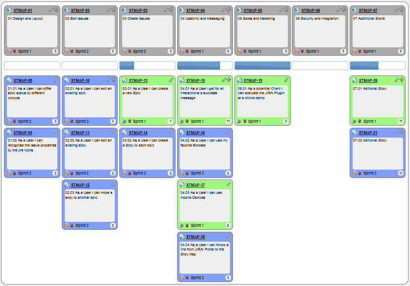
You can write user stories using a physical medium or a digital tool. For example, you can use index cards or sticky notes, and arrange them on walls or tables. Alternatively, you can use a software (e.g., GitHub Project Boards, Trello, Google Docs, ...) to manage user stories digitally.
User stories in use
With sticky notes

With paper

With software
The {benefit} can be omitted if it is obvious.
As a user, I can login to the system so that I can access my data
It is recommended to confirm there is a concrete benefit even if you omit it from the user story. If not, you could end up adding features that have no real benefit.
You can add more characteristics to the {user role} to provide more context to the user story.
- As a forgetful user, I can view a password hint, so that I can recall my password.
- As an expert user, I can tweak the underlying formatting tags of the document, so that I can format the document exactly as I need.
You can write user stories at various levels. High-level user stories, called epics (or themes) cover bigger functionality. You can then break down these epics to multiple user stories of normal size.
[Epic] As a lecturer, I can monitor student participation levels
- As a lecturer, I can view the forum post count of each student
so that I can identify the activity level of students in the forum - As a lecturer, I can view webcast view records of each student
so that I can identify the students who did not view webcasts - As a lecturer, I can view file download statistics of each student
so that I can identify the students who did not download lecture materials
You can add conditions of satisfaction to a user story to specify things that need to be true for the user story implementation to be accepted as ‘done’.
As a lecturer, I can view the forum post count of each student so that I can identify the activity level of students in the forum.
Conditions:
Separate post count for each forum should be shown
Total post count of a student should be shown
The list should be sortable by student name and post count
Other useful info that can be added to a user story includes (but not limited to)
- Priority: how important the user story is
- Size: the estimated effort to implement the user story
- Urgency: how soon the feature is needed
User stories capture user requirements in a way that is convenient for , , and .
[User stories] strongly shift the focus from writing about features to discussing them. In fact, these discussions are more important than whatever text is written. [Mike Cohn, MountainGoat Software 🔗]
User stories differ from mainly in the level of detail. User stories should only provide enough details to make a reasonably low risk estimate of how long the user story will take to implement. When the time comes to implement the user story, the developers will meet with the customer face-to-face to work out a more detailed description of the requirements. [more...]
User stories can capture non-functional requirements too because even NFRs must benefit some stakeholder.
An example of an NFR captured as a user story:
| As a/an ___, | I want to ___, | so that ___. |
|---|---|---|
| impatient user | to be able to experience reasonable response time from the website while up to 1000 concurrent users are using it | I can use the app even when the traffic is at the maximum expected level |
Given their lightweight nature, user stories are quite handy for recording requirements during early stages of requirements gathering.
A recipe for brainstorming user stories
Given below is a possible recipe you can take when using user stories for early stages of requirement gathering.
Step 0: Clear your mind of preconceived product ideas
Even if you already have some idea of what your product will look/behave like in the end, clear your mind of those ideas. The product is the solution. At this point, we are still at the stage of figuring out the problem (i.e., user requirements). Let's try to get from the problem to the solution in a systematic way, one step at a time.
Step 1: Define the target user as a persona:
Decide your target user's profile (e.g. a student, office worker, programmer, salesperson) and work patterns (e.g. Does he work in groups or alone? Does he share his computer with others?). A clear understanding of the target user will help when deciding the importance of a user story. You can even narrow it down to a persona. Here is an example:
Jean is a university student studying in a non-IT field. She interacts with a lot of people due to her involvement in university clubs/societies. ...
Step 2: Define the problem scope:
Decide the exact problem you are going to solve for the target user. It is also useful to specify what related problems it will not solve so that the exact scope is clear.
ProductX helps Jean keep track of all her school contacts. It does not cover communicating with contacts.
Step 3: List scenarios to form a narrative:
Think of the various scenarios your target user is likely to go through as she uses your app. Following a chronological sequence as if you are telling a story might be helpful.
A. First use:
- Jean gets to know about ProductX. She downloads it and launches it to check out what it can do.
- After playing around with the product for a bit, Jean wants to start using it for real.
- ...
B. Second use: (Jean is still a beginner)
- Jean launches ProductX. She wants to find ...
- ...
C. 10th use: (Jean is a little bit familiar with the app)
- ...
D. 100th use: (Jean is an expert user)
- Jean launches the app and does ... and ... followed by ... as per her usual habit.
- Jean feels some of the data in the app are no longer needed. She wants to get rid of them to reduce clutter.
More examples that might apply to some products:
- Jean uses the app at the start of the day to ...
- Jean uses the app before going to sleep to ...
- Jean hasn't used the app for a while because she was on a three-month training programme. She is now back at work and wants to resume her daily use of the app.
- Jean moves to another company. Some of her clients come with her but some don't.
- Jean starts freelancing in her spare time. She wants to keep her freelancing clients separate from her other clients.
Step 4: List the user stories to support the scenarios:
Based on the scenarios, decide on the user stories you need to support. For example, based on the scenario 'A. First use', you might have user stories such as these:
- As a potential user exploring the app, I can see the app populated with sample data, so that I can easily see how the app will look like when it is in use.
- As a user ready to start using the app, I can purge all current data, so that I can get rid of sample/experimental data I used for exploring the app.
To give another example, based on the scenario 'D. 100th use', you might have user stories such as these:
- As an expert user, I can create shortcuts for tasks, so that I can save time on frequently performed tasks.
- As a long-time user, I can archive/hide unused data, so that I am not distracted by irrelevant data.
Do not 'evaluate' the value of user stories while brainstorming. Reason: an important aspect of brainstorming is not judging the ideas generated.
Other tips:
- Don't be too hasty to discard 'unusual' user stories: Those might make your product unique and stand out from the rest, at least for the target users.
- Don't go into too much detail:
For example, consider this user story:
As a user, I want to see a list of tasks that need my attention most at the present time, so that I pay attention to them first.
When discussing this user story, don't worry about what tasks should be considered 'needs my attention most at the present time'. Those details can be worked out later. - Don't be biased by preconceived product ideas: When you are at the stage of identifying user needs, clear your mind of ideas you have about what your end product will look like. That is, don't try to reverse-engineer a preconceived product idea into user stories.
- Don't discuss implementation details or whether you are actually going to implement it: When gathering requirements, your decision is whether the user's need is important enough for you to want to fulfil it. Implementation details can be discussed later. If a user story turns out to be too difficult to implement later, you can always omit it from the implementation plan.
While use cases can be recorded on in the initial stages, an online tool is more suitable for longer-term management of user stories, especially if the team is not .
Use Cases
Use case: A description of a set of sequences of actions, including variants, that a system performs to yield an observable result of value to an actor [ 📖 : ].
A use case describes an interaction between the user and the system for a specific functionality of the system.
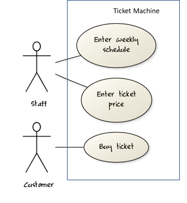
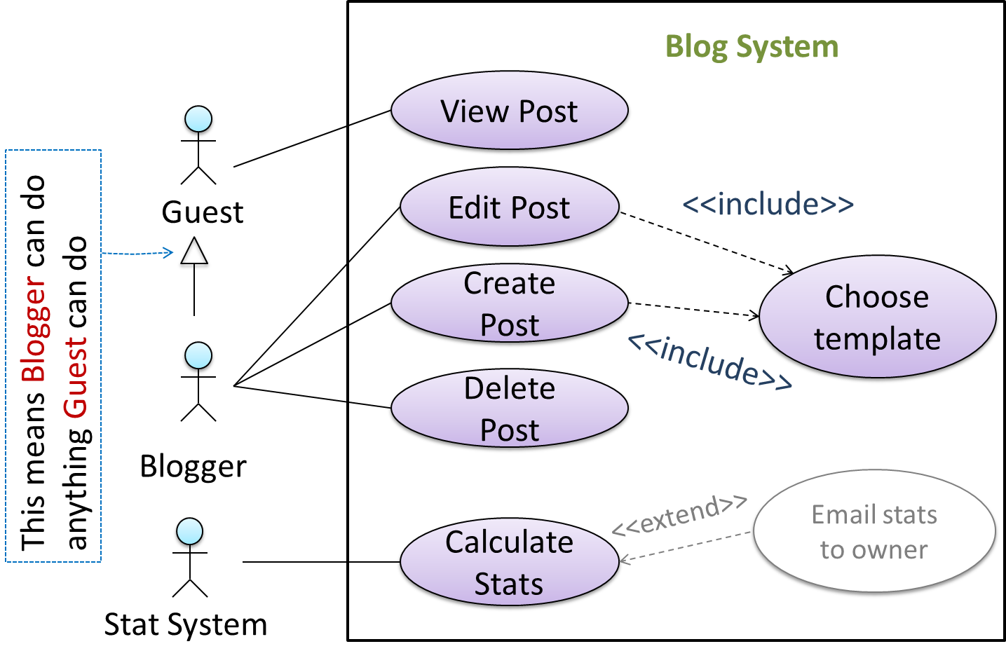
UML includes a diagram type called use case diagrams that can illustrate use cases of a system visually, providing a visual ‘table of contents’ of the use cases of a system.
In the example on the right, note how use cases are shown as ovals and user roles relevant to each use case are shown as stick figures connected to the corresponding ovals.
Use cases capture the functional requirements of a system.
A use case is an interaction between a system and its actors.
Actors in Use Cases
Actor: An actor (in a use case) is a role played by a user. An actor can be a human or another system. Actors are not part of the system; they reside outside the system.
Some example actors for a Learning Management System:
- Actors: Guest, Student, Staff, Admin, , .
A use case can involve multiple actors.
- Software System: LearnSys
- Use case: UC01 Conduct Survey
- Actors: Staff, Student
An actor can be involved in many use cases.
- Software System: LearnSys
- Actor: Staff
- Use cases: UC01 Conduct Survey, UC02 Set Up Course Schedule, UC03 Email Class, ...
A single person/system can play many roles.
- Software System: LearnSys
- Person: a student
- Actors (or Roles): Student, Guest, Tutor
Many persons/systems can play a single role.
- Software System: LearnSys
- Actor (or role): Student
- Persons that can play this role: undergraduate student, graduate student, a staff member doing a part-time course, exchange student
Use cases can be specified at various levels of detail.
Consider the three use cases given below. Clearly, (a) is at a higher level than (b) and (b) is at a higher level than (c).
- System: LearnSys
- Use cases:
a. Conduct a survey
b. Take the survey
c. Answer survey question
While modeling user-system interactions,
- start with high level use cases and progressively work toward lower level use cases.
- be mindful of which level of detail you are working at and not to mix use cases of different levels.
Writing use case steps
The main body of the use case is a sequence of steps that describes the interaction between the system and the actors. Each step is given as a simple statement describing who does what.
An example of the main body of a use case.
- Student requests to upload file
- LMS requests for the file location
- Student specifies the file location
- LMS uploads the file
A use case describes only the externally visible behavior, not internal details, of a system i.e., should minimize details that are not part of the interaction between the user and the system.
This example use case step refers to a behavior not externally visible (i.e., user is not meant to be aware of).
- LMS saves the file into the cache and indicates success.
A step gives the intention of the actor (not the mechanics). That means UI details are usually omitted. The idea is to leave as much flexibility to the UI designer as possible. That is, the use case specification should be as general as possible (less specific) about the UI.
The first example below is not a good use case step because it contains UI-specific details. The second one is better because it omits UI-specific details.
Bad : User right-clicks the text box and chooses ‘clear’
Good : User clears the input
A use case description can show loops too.
An example of how you can show a loop:
Software System: SquareGame
Use case: - Play a Game
Actors: Player (multiple players)
MSS:
- A Player starts the game.
- SquareGame asks for player names.
- Each Player enters his own name.
- SquareGame shows the order of play.
- SquareGame prompts for the current Player to throw a die.
- Current Player adjusts the throw speed.
- Current Player triggers the die throw.
- SquareGame shows the face value of the die.
- SquareGame moves the Player's piece accordingly.
Steps 5-9 are repeated for each Player, and for as many rounds as required until a Player reaches the 100th square. - SquareGame shows the Winner.
Use case ends.
The Main Success Scenario (MSS) describes the most straightforward interaction for a given use case, which assumes that nothing goes wrong. This is also called the Basic Course of Action or the Main Flow of Events of a use case.
Note how the MSS in the example below assumes that all entered details are correct and ignores problems such as timeouts, network outages etc. For example, the MSS does not tell us what happens if the user enters incorrect data.
System: Online Banking System (OBS)
Use case: UC23 - Transfer Money
Actor: User
MSS:
- User chooses to transfer money.
- OBS requests for details of the transfer.
- User enters the requested details.
- OBS requests for confirmation.
- OBS transfers the money and displays the new account balance.
Use case ends.
Extensions are "add-on"s to the MSS that describe exceptional/alternative flow of events. They describe variations of the scenario that can happen if certain things are not as expected by the MSS. Extensions appear below the MSS.
This example adds some extensions to the use case in the previous example.
System: Online Banking System (OBS)
Use case: UC23 - Transfer Money
Actor: User
MSS:
  1. User chooses to transfer money.
  2. OBS requests for details of the transfer.
  3. User enters the requested details.
  4. OBS requests for confirmation.
  5. User confirms.
  6. OBS transfers the money and displays the new account balance.
  Use case ends.
Extensions:
  3a. OBS detects an error in the entered data.
      3a1. OBS requests for the correct data.
      3a2. User enters new data.
      Steps 3a1-3a2 are repeated until the data entered are correct.
      Use case resumes from step 4.

  3b. User requests to effect the transfer in a future date.
      3b1. OBS requests for confirmation.
      3b2. User confirms future transfer.
      Use case ends.

  *a. At any time, User chooses to cancel the transfer.
      *a1. OBS requests to confirm the cancellation.
      *a2. User confirms the cancellation.
      Use case ends.
*b. At any time, 120 seconds lapse without any input from the User.
*b1. OBS cancels the transfer.
*b2. OBS informs the User of the cancellation.
Use case ends.
Note that the numbering style is not a universal rule but a widely used convention. Based on that convention,
- either of the extensions marked
3a.and3b.can happen just after step3of the MSS. - the extension marked as
*a.can happen at any step (hence, the*).
When separating extensions from the MSS, keep in mind that the MSS should be self-contained. That is, the MSS should give us a complete usage scenario.
Also note that it is not useful to mention events such as power failures or system crashes as extensions because the system cannot function beyond such catastrophic failures.
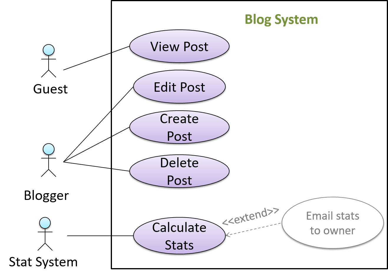
In use case diagrams you can use the <<extend>> arrows to show extensions. Note the direction of the arrow is from the extension to the use case it extends and the arrow uses a dashed line.
A use case can include another use case. Underlined text is used to show an inclusion of a use case.
This use case includes two other use cases, one in step 1 and one in step 2.
- Software System: LearnSys
- Use case: UC01 - Conduct Survey
- Actors: Staff, Student
- MSS:
- Staff creates the survey (UC44).
- Student completes the survey (UC50).
- Staff views the survey results.
Use case ends.
Inclusions are useful,
- when you don't want to clutter a use case with too many low-level steps.
- when a set of steps is repeated in multiple use cases.
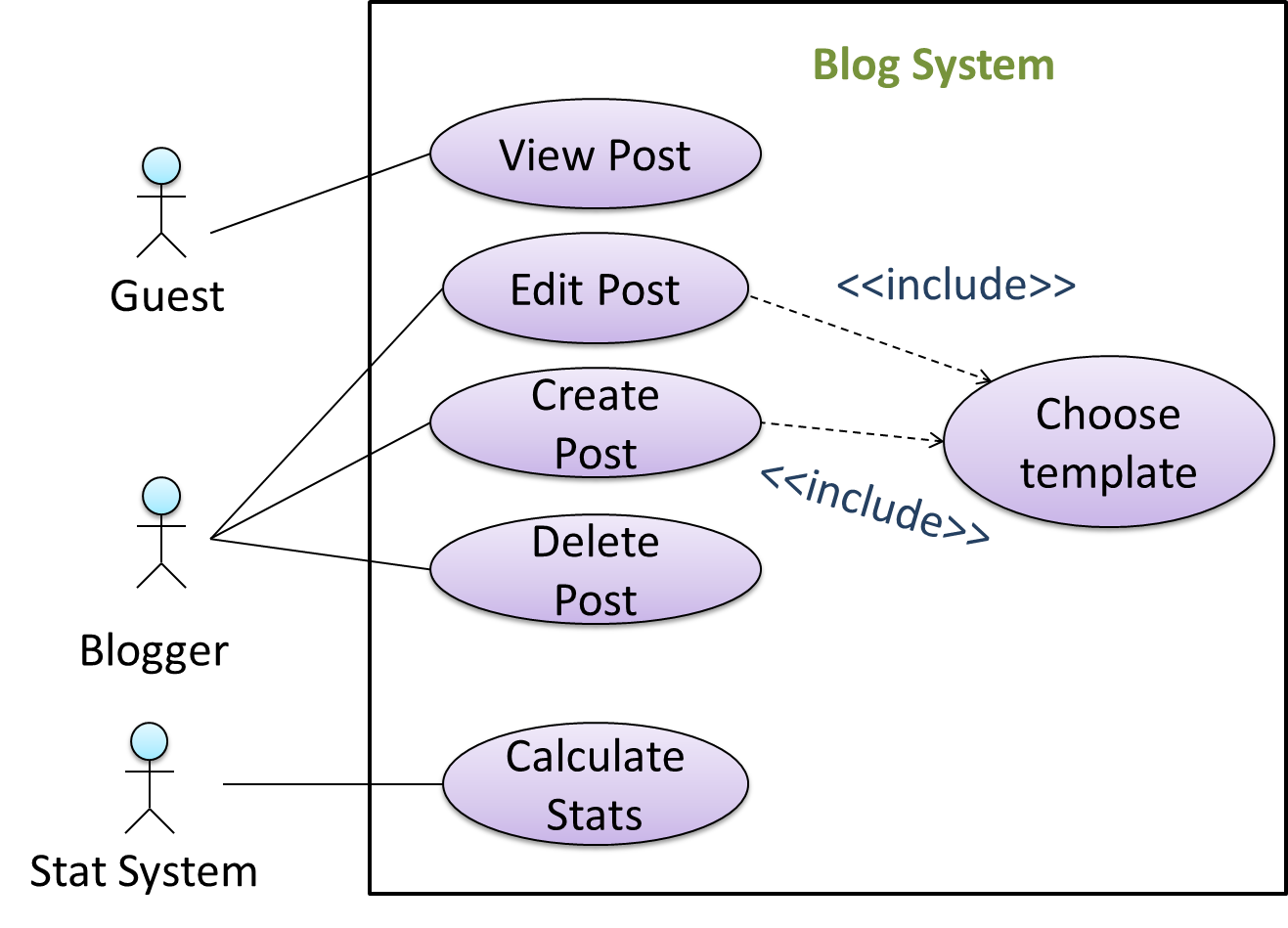
You use a dotted arrow and an <<include>> annotation to show use case inclusions in a use case diagram. Note how the arrow direction is different from the <<extend>> arrows.
Preconditions specify the specific state you expect the system to be in before the use case starts.
Software System: Online Banking System
Use case: UC23 - Transfer Money
Actor: User
Preconditions: User is logged in
MSS:
- User chooses to transfer money.
- OBS requests for details for the transfer.
...
Guarantees specify what the use case promises to give us at the end of its operation.
Software System: Online Banking System
Use case: UC23 - Transfer Money
Actor: User
Preconditions: User is logged in.
Guarantees:
- Money will be deducted from the source account only if the transfer to the destination account is successful.
- The transfer will not result in the account balance going below the minimum balance required.
MSS:
- User chooses to transfer money.
- OBS requests for details for the transfer.
...
You can use actor generalization in use case diagrams using a symbol similar to that of UML notation for inheritance.
In this example, actor Blogger can do all the use cases the actor Guest can do, as a result of the actor generalization relationship given in the diagram.
Do not over-complicate use case diagrams by trying to include everything possible. A use case diagram is a brief summary of the use cases that is used as a starting point. Details of the use cases can be given in the use case descriptions.
Some include ‘System’ as an actor to indicate that something is done by the system itself without being initiated by a user or an external system.
The diagram below can be used to indicate that the system generates daily reports at midnight.
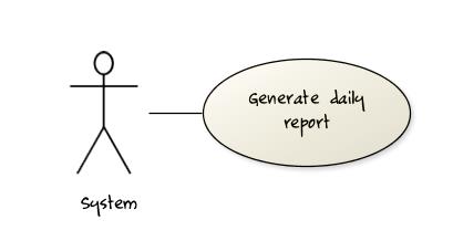
However, others argue that only use cases providing value to an external user/system should be shown in the use case diagram. For example, they argue that view daily report should be the use case and generate daily report is not to be shown in the use case diagram because it is simply something the system has to do to support the view daily report use case.
You are recommended to follow the latter view (i.e., not to use System as a user). Limit use cases for modeling behaviors that involve an external actor.
UML is not very specific about the text contents of a use case. Hence, there are many styles for writing use cases. For example, the steps can be written as a continuous paragraph.
Use cases should be easy to read. Note that there is no strict rule about writing all details of all steps or a need to use all the elements of a use case.
There are some advantages of documenting system requirements as use cases:
- Because they use a simple notation and plain English descriptions, they are easy for users to understand and give feedback.
- They decouple user intention from mechanism (note that use cases should not include UI-specific details), allowing the system designers more freedom to optimize how a functionality is provided to a user.
- Identifying all possible extensions encourages us to consider all situations that a software product might face during its operation.
- Separating typical scenarios from special cases encourages us to optimize the typical scenarios.
One of the main disadvantages of use cases is that they are not good for capturing requirements that do not involve a user interacting with the system. Hence, they should not be used as the sole means to specify requirements.
Glossary
Glossary: A glossary serves to ensure that all stakeholders have a common understanding of the noteworthy terms, abbreviations, acronyms etc.
Here is a partial glossary from a variant of the Snakes and Ladders game:
- Conditional square: A square that specifies a specific face value which a player has to throw before his/her piece can leave the square.
- Normal square: a normal square does not have any conditions, snakes, or ladders in it.
Supplementary Requirements
SECTION: DESIGN
Design
Introduction
Design is the creative process of transforming the problem into a solution; the solution is also called design. -- 📖 Software Engineering Theory and Practice, Shari Lawrence; Atlee, Joanne M. Pfleeger
Software design has two main aspects:
- Product/external design: designing the external behavior of the product to meet the users' requirements. This is usually done by product designers with input from business analysts, user experience experts, user representatives, etc.
- Implementation/internal design: designing how the product will be implemented to meet the required external behavior. This is usually done by software architects and software engineers.
Design Fundamentals
Abstraction
Abstraction is a technique for dealing with complexity. It works by establishing a level of complexity we are interested in, and suppressing the more complex details below that level.
The guiding principle of abstraction is that only details that are relevant to the current perspective or the task at hand need to be considered. As most programs are written to solve complex problems involving large amounts of intricate details, it is impossible to deal with all these details at the same time. That is where abstraction can help.
Data abstraction: abstracting away the lower level data items and thinking in terms of bigger entities
Within a certain software component, you might deal with a user data type, while ignoring the details contained in the user data item such as name, and date of birth. These details have been ‘abstracted away’ as they do not affect the task of that software component.
Control abstraction: abstracting away details of the actual control flow to focus on tasks at a higher level
print(“Hello”) is an abstraction of the actual output mechanism within the computer.
Abstraction can be applied repeatedly to obtain progressively higher levels of abstraction.
An example of different levels of data abstraction: a File is a data item that is at a higher level than an array and an array is at a higher level than a bit.
An example of different levels of control abstraction: execute(Game) is at a higher level than print(Char) which is at a higher level than an Assembly language instruction MOV.
Abstraction is a general concept that is not limited to just data or control abstractions.
Some more general examples of abstraction:
- An OOP class is an abstraction over related data and behaviors.
- An architecture is a higher-level abstraction of the design of a software.
- Models (e.g., UML models) are abstractions of some aspect of reality.
Coupling
Coupling is a measure of the degree of dependence between components, classes, methods, etc. Low coupling indicates that a component is less dependent on other components. High coupling (aka tight coupling or strong coupling) is discouraged due to the following disadvantages:
- Maintenance is harder because a change in one module could cause changes in other modules coupled to it (i.e., a ripple effect).
- Integration is harder because multiple components coupled with each other have to be integrated at the same time.
- Testing and reuse of the module is harder due to its dependence on other modules.
In the example below, design A appears to have more coupling between the components than design B.
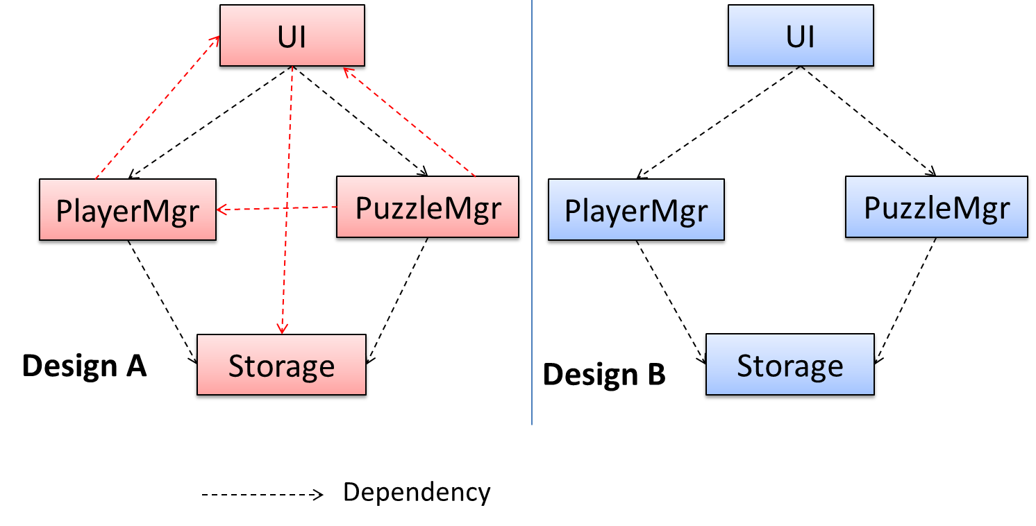
X is coupled to Y if a change to Y can potentially require a change in X.
If the Foo class calls the method Bar#read(), Foo is coupled to Bar because a change to Bar can potentially (but not always) require a change in the Foo class e.g. if the signature of Bar#read() is changed, Foo needs to change as well, but a change to the Bar#write() method may not require a change in the Foo class because Foo does not call Bar#write().
Some examples of coupling: A is coupled to B if,
Ahas access to the internal structure ofB(this results in a very high level of coupling)AandBdepend on the same global variableAcallsBAreceives an object ofBas a parameter or a return valueAinherits fromBAandBare required to follow the same data format or communication protocol
Some examples of different coupling types:
- Content coupling: one module modifies or relies on the internal workings of another module e.g., accessing local data of another module
- Common/Global coupling: two modules share the same global data
- Control coupling: one module controlling the flow of another, by passing it information on what to do e.g., passing a flag
- Data coupling: one module sharing data with another module e.g. via passing parameters
- External coupling: two modules share an externally imposed convention e.g., data formats, communication protocols, device interfaces.
- Subclass coupling: a class inherits from another class. Note that a child class is coupled to the parent class but not the other way around.
- Temporal coupling: two actions are bundled together just because they happen to occur at the same time e.g. extracting a contiguous block of code as a method although the code block contains statements unrelated to each other
Cohesion
Cohesion is a measure of how strongly-related and focused the various responsibilities of a component are. A highly-cohesive component keeps related functionalities together while keeping out all other unrelated things.
Higher cohesion is better. Disadvantages of low cohesion (aka weak cohesion):
- Lowers the understandability of modules as it is difficult to express module functionalities at a higher level.
- Lowers maintainability because a module can be modified due to unrelated causes (reason: the module contains code unrelated to each other) or many modules may need to be modified to achieve a small change in behavior (reason: because the code related to that change is not localized to a single module).
- Lowers reusability of modules because they do not represent logical units of functionality.
Cohesion can be present in many forms. Some examples:
- Code related to a single concept is kept together, e.g. the
Studentcomponent handles everything related to students. - Code that is invoked close together in time is kept together, e.g. all code related to initializing the system is kept together.
- Code that manipulates the same data structure is kept together, e.g. the
GameArchivecomponent handles everything related to the storage and retrieval of game sessions.
Suppose a Payroll application contains a class that deals with writing data to the database. If the class includes some code to show an error dialog to the user if the database is unreachable, that class is not cohesive because it seems to be interacting with the user as well as the database.
Modeling
Introduction
A model is a representation of something else.
A class diagram is a model that represents a software design.
A model provides a simpler view of a complex entity because a model captures only a selected aspect. This omission of some aspects implies models are abstractions.
A class diagram captures the structure of the software design but not the behavior.
Multiple models of the same entity may be needed to capture it fully.
In addition to a class diagram (or even multiple class diagrams), a number of other diagrams may be needed to capture various interesting aspects of the software.
In software development, models are useful in several ways:
a) To analyze a complex entity related to software development.
Some examples of using models for analysis:
- Models of the can be built to aid the understanding of the problem to be solved.
- When planning a software solution, models can be created to figure out how the solution is to be built. An architecture diagram is such a model.
b) To communicate information among stakeholders. Models can be used as a visual aid in discussions and documentation.
Some examples of using models to communicate:
- You can use an architecture diagram to explain the high-level design of the software to developers.
- A business analyst can use a use case diagram to explain to the customer the functionality of the system.
- A class diagram can be reverse-engineered from code so as to help explain the design of a component to a new developer.
c) As a blueprint for creating software. Models can be used as instructions for building software.
Some examples of using models as blueprints:
- A senior developer draws a class diagram to propose a design for an OOP software and passes it to a junior programmer to implement.
- A software tool allows users to draw UML models using its interface and the tool automatically generates the code based on the model.
Unified Modeling Language (UML) is a graphical notation to describe various aspects of a software system. UML is the brainchild of three software modeling specialists James Rumbaugh, Grady Booch and Ivar Jacobson (also known as the Three Amigos). Each of them had developed their own notation for modeling software systems before joining forces to create a unified modeling language (hence, the term ‘Unified’ in UML). UML is currently the most commonly used modeling notation used in the software industry.
The following diagram uses the class diagram notation to show the different types of UML diagrams.

source:https://en.wikipedia.org/
Modeling Structures
Classes form the basis of class diagrams.
Associations are the main connections among the classes in a class diagram.
The most basic class diagram is a bunch of classes with some solid lines among them to represent associations, such as this one.
An example class diagram showing associations between classes.
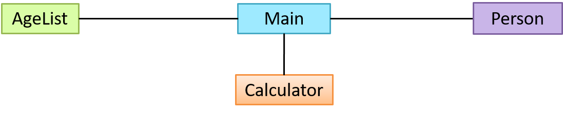
In addition, associations can show additional decorations such as association labels, association roles, multiplicity and navigability to add more information to a class diagram.
Here is the same class diagram shown earlier but with some additional information included:
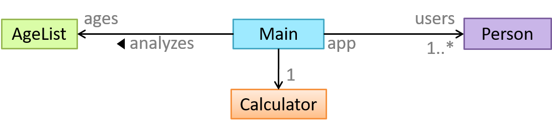
A class diagram can also show different types of relationships between classes: inheritance, compositions, aggregations, dependencies.
A class diagram can also show different types of class-like entities:
Object diagrams can be used to complement class diagrams. For example, you can use object diagrams to model different object structures that can result from a design represented by a given class diagram.
The analysis process for identifying objects and object classes is recognized as one of the most difficult areas of object-oriented development. --Ian Sommerville, in the book Software Engineering
Sidebar: Domain Modeling
Domain modeling is modeling the i.e., to model how things actually work in the real world. Domain modeling is useful in understanding the problem domain, which is essential to the success of a project.
Domain modeling can be done using,
- a domain-specific modeling notation if such a notation exists (e.g., a modeling notation specific to the banking domain might have elements to represent loans, accounts, transactions etc.),
- or a general purpose modeling notation, such as UML (e.g., you can use an activity diagram to model the workflow of processing a loan application),
- or even other general purpose notations (e.g., you can use an organization chart to model the employee hierarchy of a company).
When building an OOP system, it makes sense to build OOP models of the problem domain, given OOP aspires to emulate the objects in the real world.
The UML model that captures class structures in the problem domain are called conceptual class diagrams. They are in fact a lighter version of class diagrams, and sometimes also called OO domain models (OODMs). The latter name is somewhat misleading as conceptual class diagrams (CCDs) are actually only one type of domain models that can model an OOP problem domain.
The CCD of a snakes and ladders game is given below.
Description: The snakes and ladders game is played by two or more players using a board and a die. The board has 100 squares marked 1 to 100. Each player owns one piece. Players take turns to throw the die and advance their piece by the number of squares they earned from the die throw. The board has a number of snakes. If a player’s piece lands on a square with a snake head, the piece is automatically moved to the square containing the snake’s tail. Similarly, a piece can automatically move from a ladder foot to the ladder top. The player whose piece is the first to reach the 100th square wins.
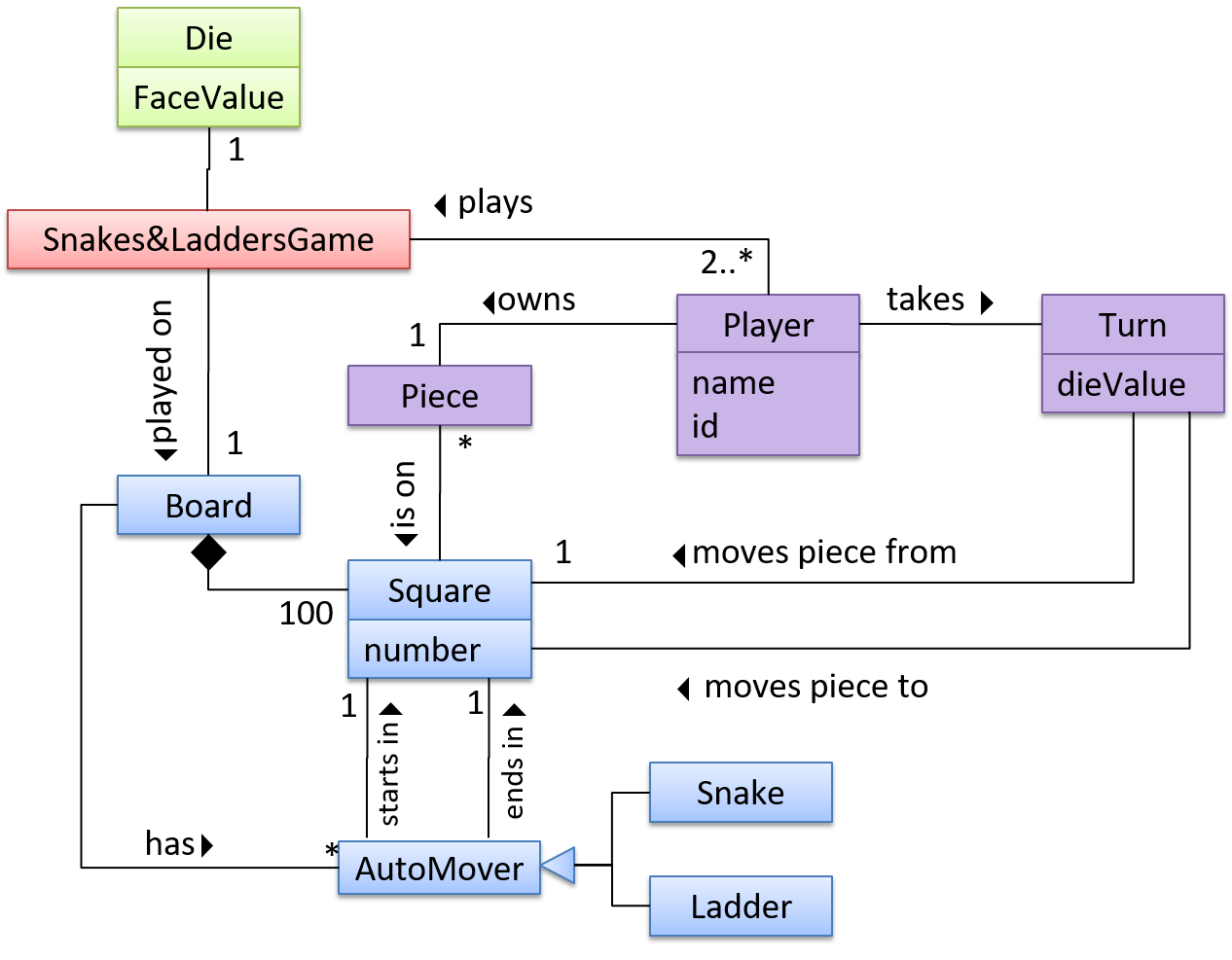
CCDs do not contain solution-specific classes (i.e., classes that are used in the solution domain but do not exist in the problem domain). For example, a class called DatabaseConnection could appear in a class diagram but not usually in a CCD because DatabaseConnection is something related to a software solution but not an entity in the problem domain.
CCDs represents the class structure of the problem domain and not their behavior, just like class diagrams. To show behavior, use other diagrams such as sequence diagrams.
CCD notation is a subset of the class diagram notation (omits methods and navigability).
A deployment diagram shows a system's physical layout, revealing which pieces of software run on which pieces of hardware.
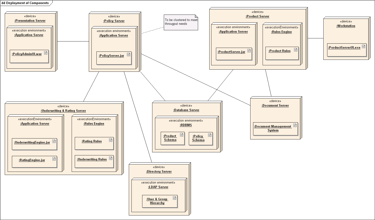
A component diagram is used to show how a system is divided into components and how they are connected to each other through interfaces.
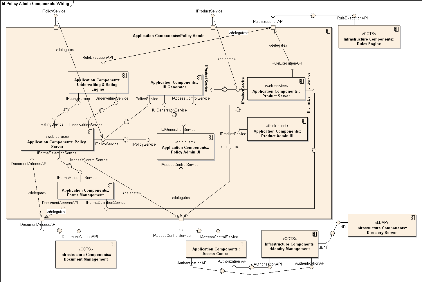
A package diagram shows packages and their dependencies. A package is a grouping construct for grouping UML elements (classes, use cases, etc.).
Here is an example package diagram:
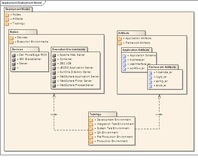
A composite structure diagram hierarchically decomposes a class into its internal structure.
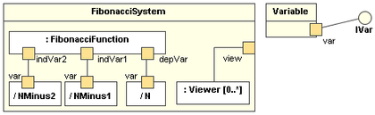
Modeling Behaviors
Software projects often involve workflows. Workflows define the flow in which a process or a set of tasks is executed. Understanding such workflows is important for the success of the software project.
Some examples in which a certain workflow is relevant to software project:
A software that automates the work of an insurance company needs to take into account the workflow of processing an insurance claim.
The algorithm of a piece of code represents the workflow (i.e., the execution flow) of the code.
Sequence diagrams model the interactions between various entities in a system, in a specific scenario. Modelling such scenarios is useful, for example, to verify the design of the internal interactions is able to provide the expected outcomes.
Some examples where a sequence diagram can be used:
To model how components of a system interact with each other to respond to a user action.
To model how objects inside a component interact with each other to respond to a method call it received from another component.
Use case diagrams model the mapping between features of a system and its user roles i.e., which user roles can perform which tasks using the software.
A simple use case diagram:
A timing diagram focuses on timing constraints.
Here is an example timing diagram:
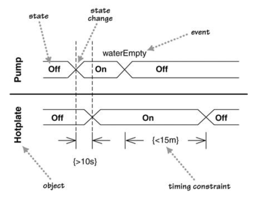
Adapted from: UML Distilled by Martin Fowler
Interaction overview diagrams are a combination of activity diagrams and sequence diagrams.
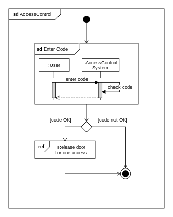
Communication diagrams are like sequence diagrams but emphasize the data links between the various participants in the interaction rather than the sequence of interactions.
An example:
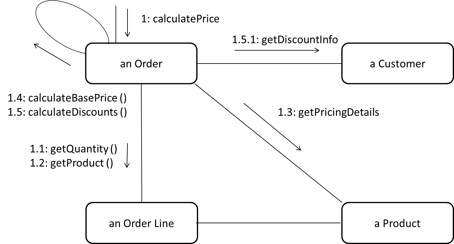
Adapted from: UML Distilled by Martin Fowler
A State Machine Diagram models state-dependent behavior.
Consider how a CD player responds when the “eject CD” button is pushed:
- If the CD tray is already open, it does nothing.
- If the CD tray is already in the process of opening (opened half-way), it continues to open the CD tray.
- If the CD tray is closed and the CD is being played, it stops playing and opens the CD tray.
- If the CD tray is closed and CD is not being played, it simply opens the CD tray.
- If the CD tray is already in the process of closing (closed half-way), it waits until the CD tray is fully closed and opens it immediately afterwards.
What this means is that the CD player’s response to pushing the “eject CD” button depends on what it was doing at the time of the event. More generally, the CD player’s response to the event received depends on its internal state. Such a behavior is called a state-dependent behavior.
Often, state-dependent behavior displayed by an object in a system is simple enough that it needs no extra attention; such a behavior can be as simple as a conditional behavior like if x > y, then x = x - y.
Occasionally, objects may exhibit state-dependent behavior that is complex enough such that it needs to be captured in a separate model. Such state-dependent behavior can be modeled using UML state machine diagrams (SMD for short, sometimes also called ‘state charts’, ‘state diagrams’ or ‘state machines’).
An SMD views the life-cycle of an object as consisting of a finite number of states where each state displays a unique behavior pattern. SMDs capture information such as the states an object can be in during its lifetime, how the object responds to various events while in each state, and how the object transits from one state to another. In contrast to sequence diagrams that capture object behavior one scenario at a time, SMDs capture the object’s behavior over its full life-cycle.
An SMD for the Minesweeper game.
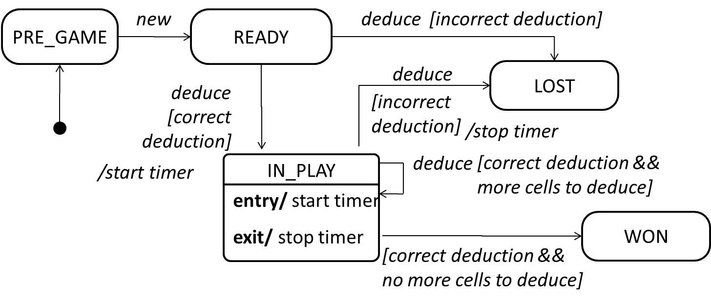
Modeling a Solution
You can use models to analyze and design software before you start coding.
Suppose you are planning to implement a simple minesweeper game that has a text based UI and a GUI. Given below is a possible OOP design for the game.

Before jumping into coding, you may want to find out things such as,
- Is this class structure able to produce the behavior you want?
- What API should each class have?
- Do you need more classes?
To answer these questions, you can analyze how the objects of these classes will interact with each other to produce the behavior you want.
As mentioned in [Design → Modeling → Modeling a Solution → Introduction], this is the Minesweeper design you have come up with so far. Our objective is to analyze, evaluate, and refine that design.
Let us start by modeling a sample interaction between the person playing the game and the TextUi object.
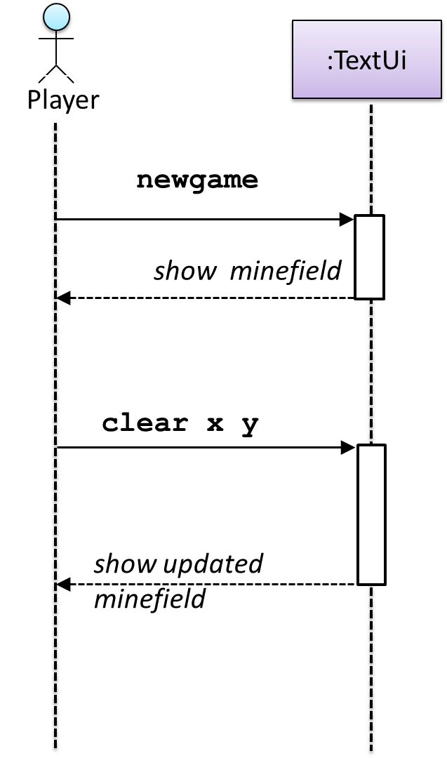
newgame and clear x y represent commands typed by the Player on the TextUi.
How does the TextUi object carry out the requests it has received from the player? It would need to interact with other objects of the system. Because the Logic class is the one that controls the game logic, the TextUi needs to collaborate with Logic to fulfill the newgame request. Let us extend the model to capture that interaction.
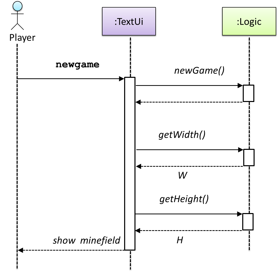
W = Width of the minefield; H = Height of the minefield
The above diagram assumes that W and H are the only information TextUi requires to display the minefield to the Player. Note that there could be other ways of doing this.
The Logic methods you conceptualized in our modeling so far are:
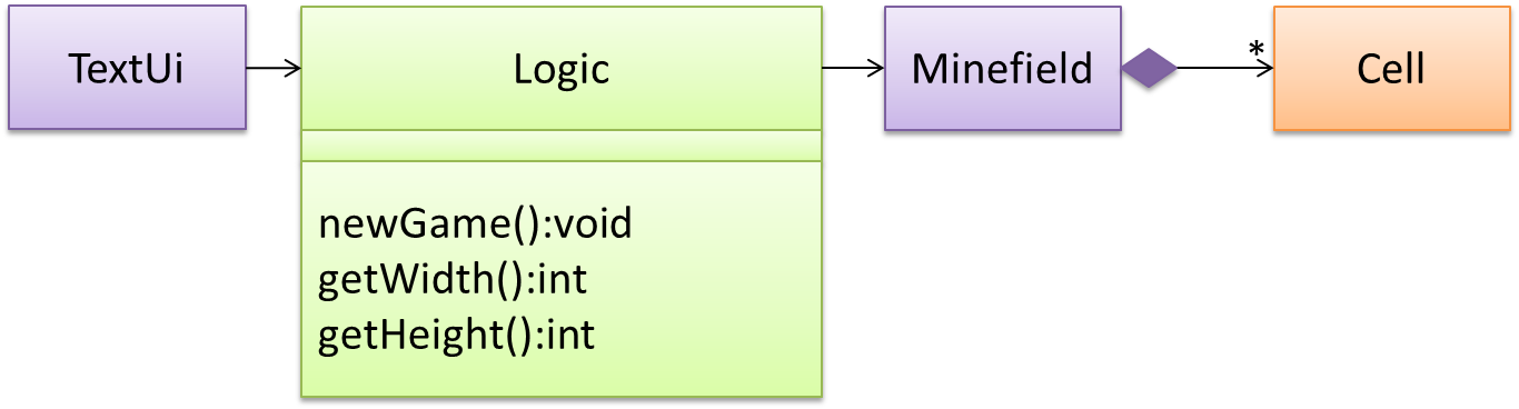
Now, let us look at what other objects and interactions are needed to support the newGame() operation. It is likely that a new Minefield object is created when the newGame() method is called.
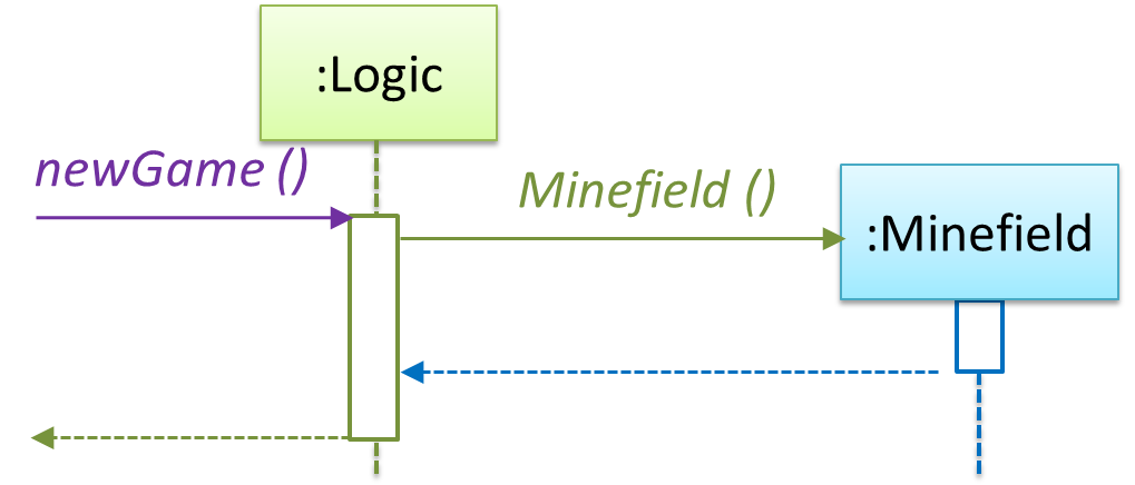
Note that the behavior of the Minefield constructor has been abstracted away. It can be designed at a later stage.
Given below are the interactions between the player and the TextUi for the whole game.
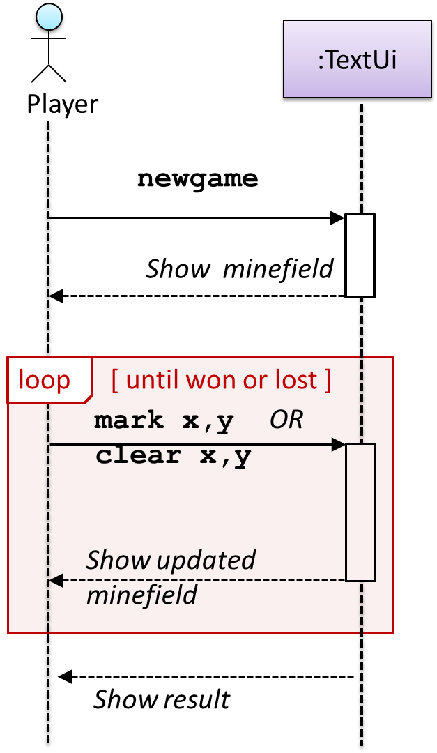
Note that can be used when discovering/defining the architecture-level APIs.
Defining the architecture-level APIs for a small Tic-Tac-Toe game:
Continuing with the example in [Design → Modeling → Modeling a Solution → Basic], next let us model how the TextUi interacts with the Logic to support the mark and clear operations until the game is won or lost.
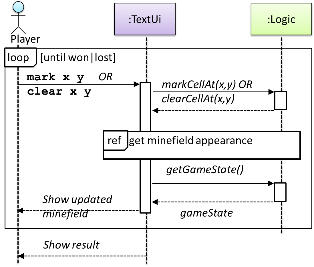
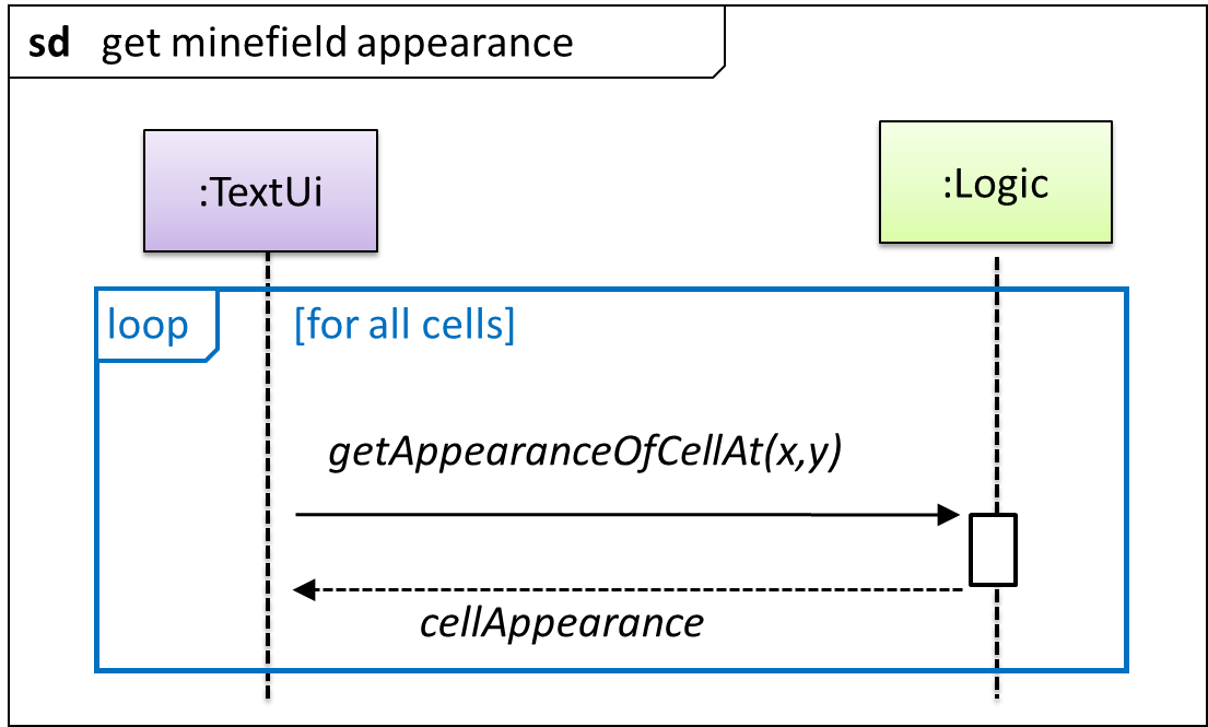
This interaction adds the following methods to the Logic class:
clearCellAt(int x, int y)markCellAt(int x, int y)getGameState(): GAME_STATE (GAME_STATE: READY, IN_PLAY, WON, LOST, …)
And it adds the following operation to Logic API:
getAppearanceOfCellAt(int,int): CELL_APPEARANCE (CELL_APPEARANCE: HIDDEN, ZERO, ONE, TWO, THREE, …, MARKED, INCORRECTLY_MARKED, INCORRECTLY_CLEARED)
In the above design, TextUi does not access Cell objects directly. Instead, it gets values of type CELL_APPEARANCE from Logic to be displayed as a minefield to the player. Alternatively, each cell or the entire minefield can be passed directly to TextUi.
Here is the updated class diagram:
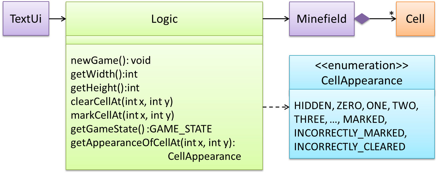
The above is for the case when Actor Player interacts with the system using a text UI. Additional operations (if any) required for the GUI can be discovered similarly.
Suppose Logic supports a reset() operation. You can model it like this:
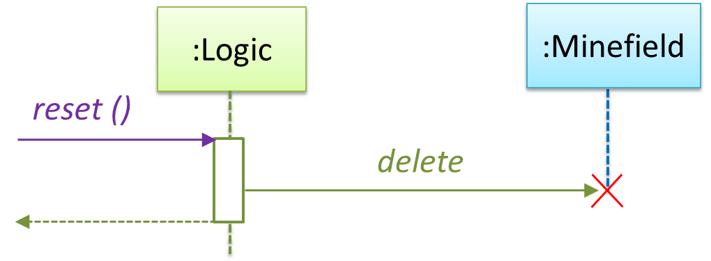
Our current model assumes that the Minefield object has enough information (i.e., H, W, and mine locations) to create itself.
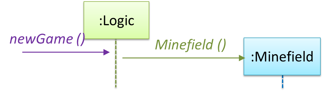
An alternative is to have a ConfigGenerator object that generates a string containing the minefield information as shown below.
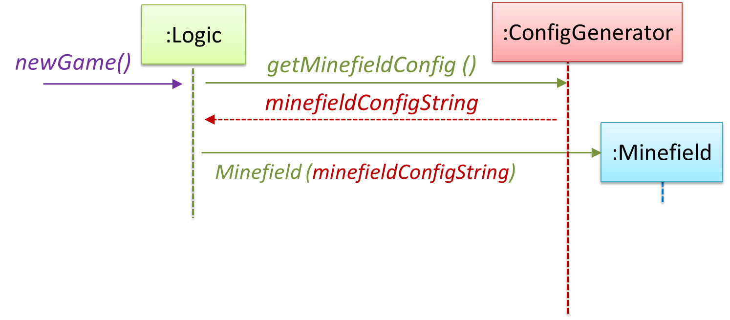
In addition, getWidth(), getHeight(), markCellAt(x,y) and clearCellAt(x,y) can be handled like this.
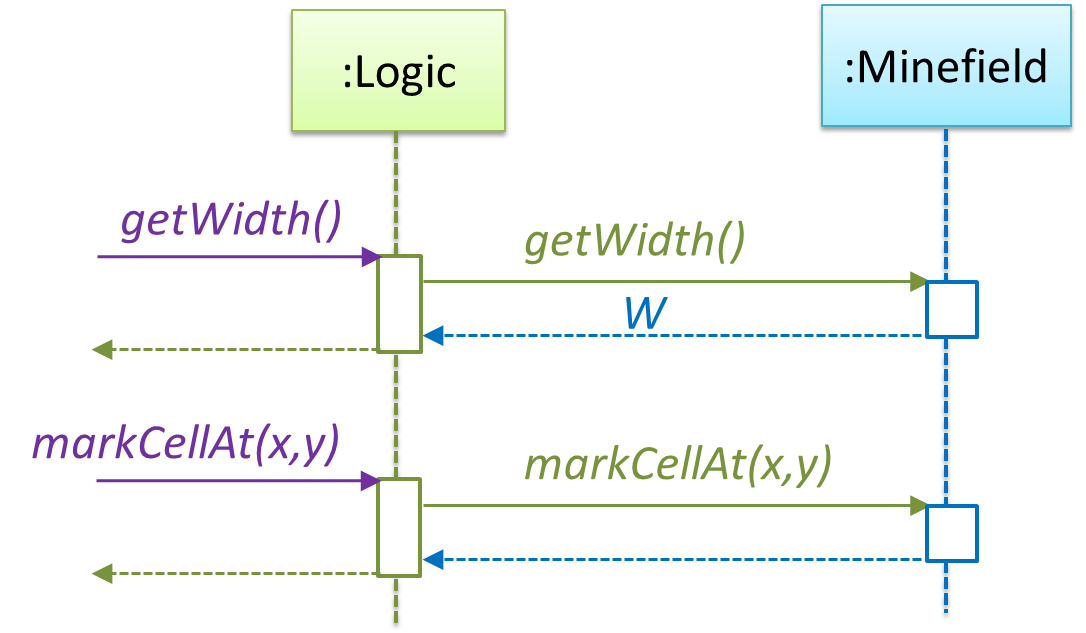
The updated class diagram:
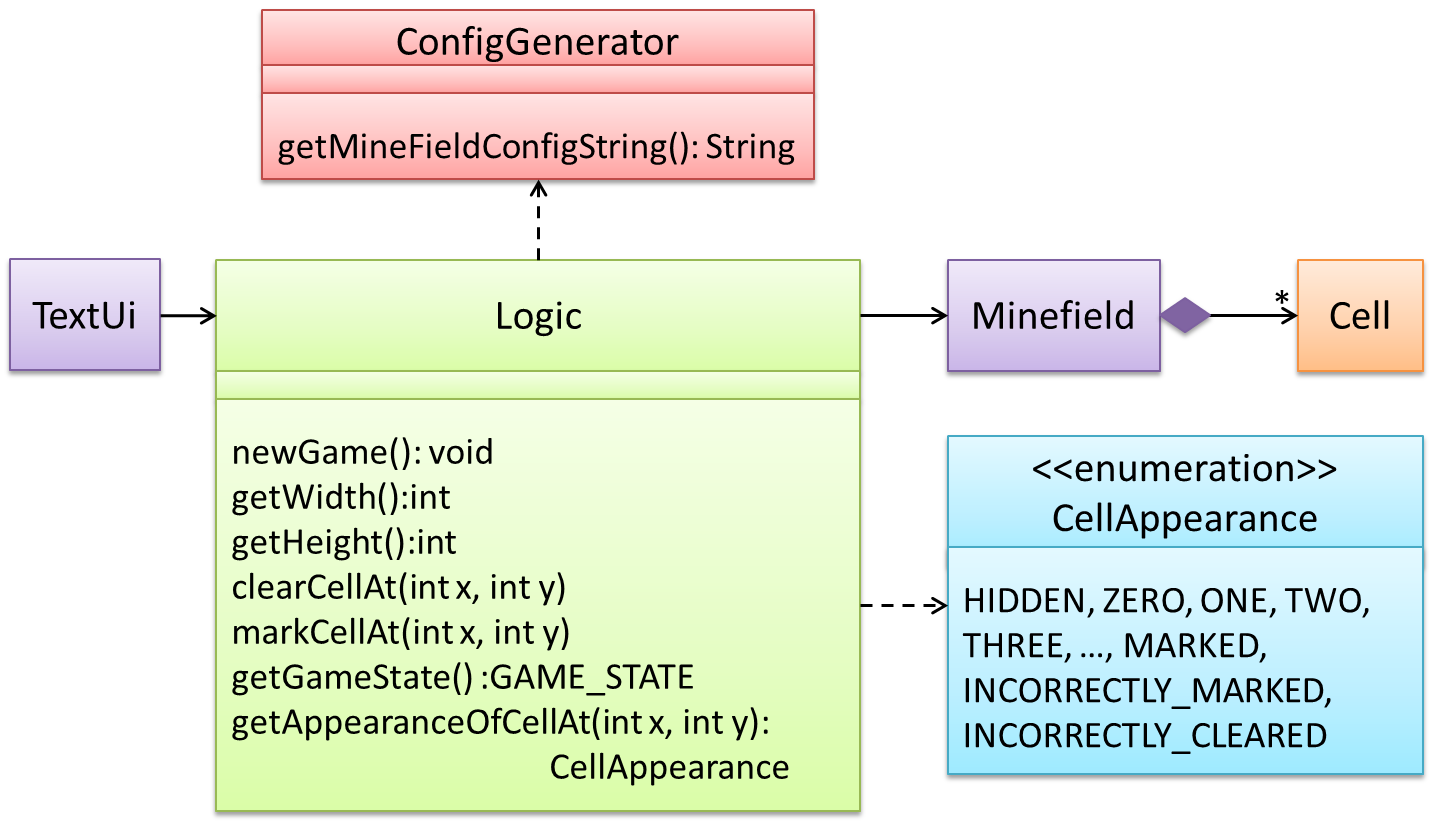
How is the getGameState() operation supported? Given below are two ways (there could be other ways):
- The
Minefieldclass knows the state of the game at any time. TheLogicclass retrieves it from theMinefieldclass as and when required. - The
Logicclass maintains the state of the game at all times.
Here’s the SD for option 1.
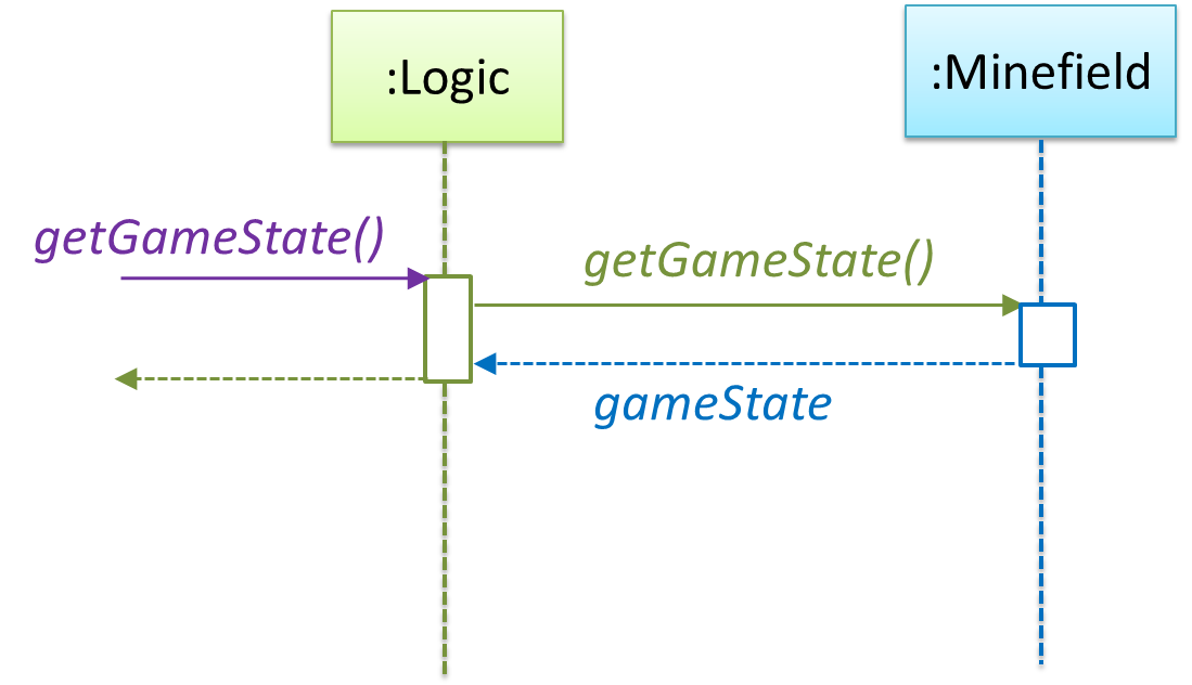
Here’s the SD for option 2. Assume that the game state is updated after every mark/clear action.
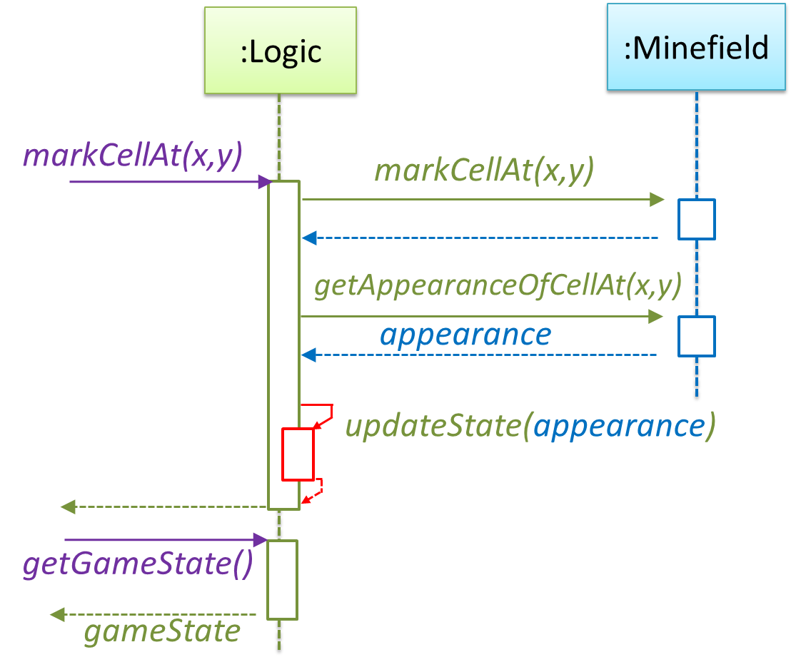
It is now time to explore what happens inside the Minefield constructor. One way is to design it as follows.
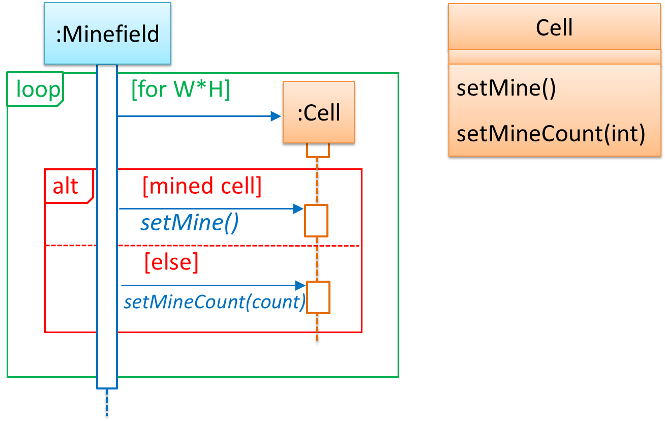
Now let us assume that Minesweeper supports a ‘timing’ feature.
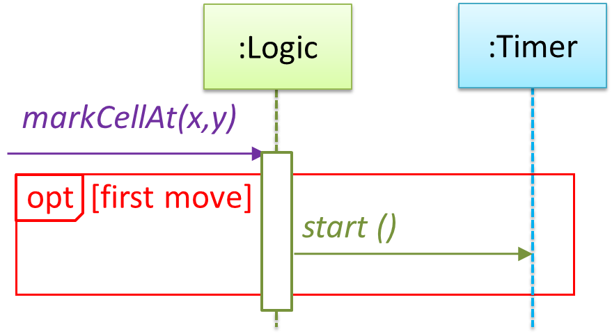
Updated class diagram:
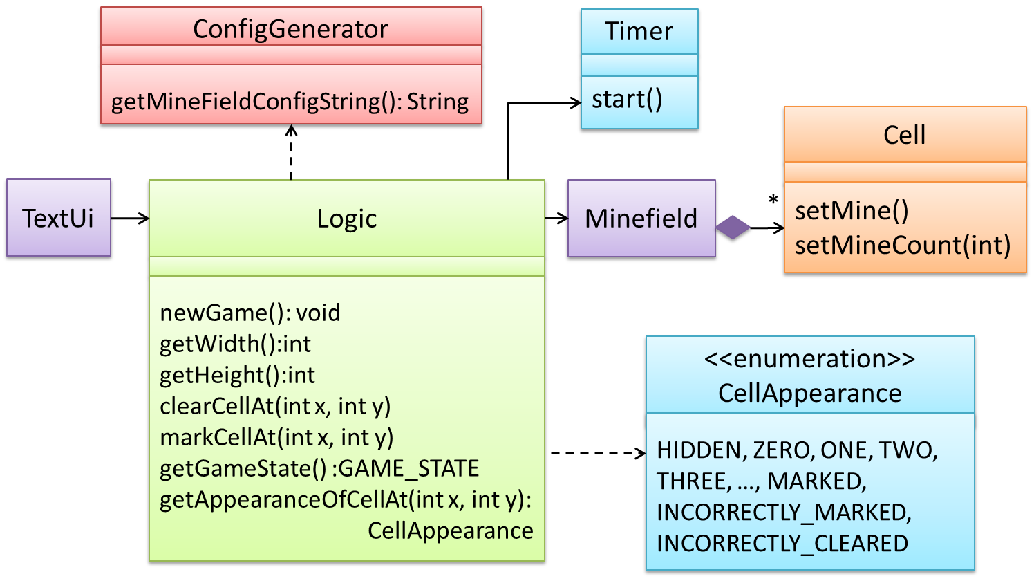
When designing components, it is not necessary to draw elaborate UML diagrams capturing all details of the design. They can be done as rough sketches. For example, draw sequence diagrams only when you are not sure which operations are required by each class, or when you want to verify that your class structure can indeed support the required operations.
Software Architecture
Introduction
The software architecture of a program or computing system is the structure or structures of the system, which comprise software elements, the externally visible properties of those elements, and the relationships among them. Architecture is concerned with the public side of interfaces; private details of elements—details having to do solely with internal implementation—are not architectural. -- Software Architecture in Practice (2nd edition), Bass, Clements, and Kazman
The software architecture shows the overall organization of the system and can be viewed as a very high-level design. It usually consists of a set of interacting components that fit together to achieve the required functionality. It should be a simple and technically viable structure that is well-understood and agreed-upon by everyone in the development team, and it forms the basis for the implementation.
A possible architecture for a Minesweeper game:
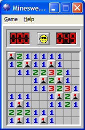 | 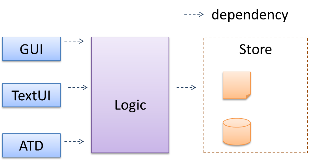 |
Main components:
GUI: Graphical user interfaceTextUi: Textual user interfaceATD: An automated test driver used for testing the game logicLogic: Computation and logic of the gameStore: Storage and retrieval of game data (high scores etc.)
The architecture is typically designed by the software architect, who provides the technical vision of the system and makes high-level (i.e., architecture-level) technical decisions about the project.
Architecture Diagrams
Architecture diagrams are free-form diagrams. There is no universally adopted standard notation for architecture diagrams. Any symbols that reasonably describe the architecture may be used.
Some example architecture diagrams:
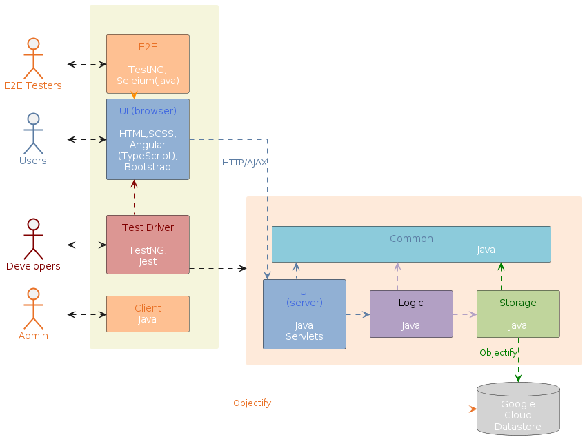


While architecture diagrams have no standard notation, try to follow these basic guidelines when drawing them.
Minimize the variety of symbols. If the symbols you choose do not have widely-understood meanings e.g., A drum symbol is widely-understood as representing a database, explain their meaning.
Avoid the indiscriminate use of double-headed arrows to show interactions between components.
Consider the two architecture diagrams of the same software given below. Because Diagram 2 uses double-headed arrows, the important fact that GUI has a bidirectional dependency with the Logic component is no longer captured.
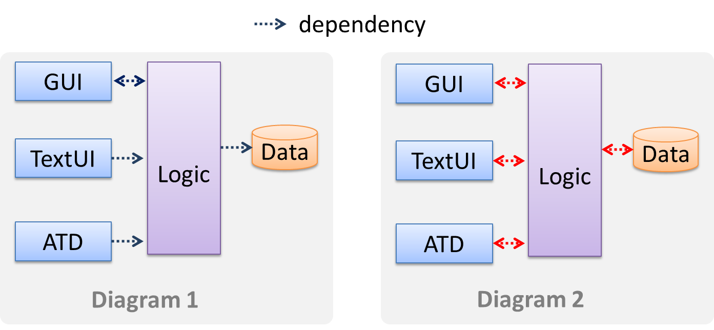
Architectural Styles
Introduction
Software architectures follow various high-level styles (aka architectural patterns), just like how building architectures follow various architecture styles.
n-tier style, client-server style, event-driven style, transaction processing style, service-oriented style, pipes-and-filters style, message-driven style, broker style, ...
N-tier Architectural Style
In the n-tier style, higher layers make use of services provided by lower layers. Lower layers are independent of higher layers. Other names: multi-layered, layered.
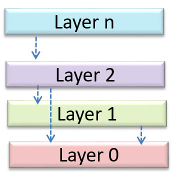
Operating systems and network communication software often use n-tier style.
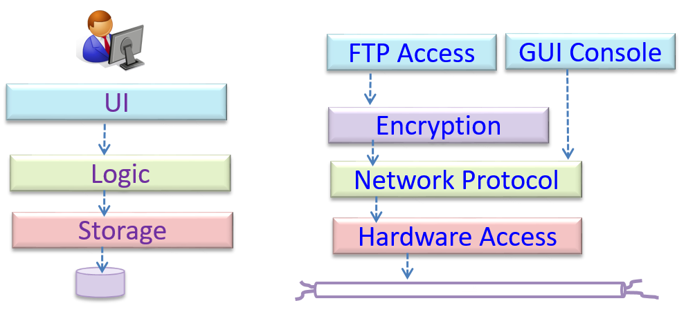
Client-Server Architectural Style
The client-server style has at least one component playing the role of a server and at least one client component accessing the services of the server. This is an architectural style used often in distributed applications.
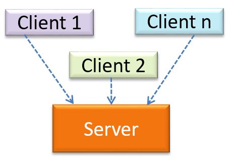
The online game and the web application below use the client-server style.
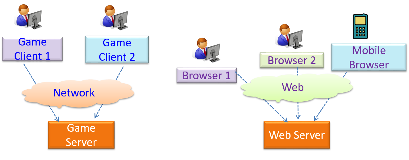
Transaction Processing Architectural Style
The transaction processing style divides the workload of the system down to a number of transactions which are then given to a dispatcher that controls the execution of each transaction. Task queuing, ordering, undo etc. are handled by the dispatcher.
In this example from a banking system, transactions are generated by the terminals used by , which are then sent to a central dispatching unit, which in turn dispatches the transactions to various other units to execute.
Service-oriented Architectural Style
The service-oriented architecture (SOA) style builds applications by combining functionalities packaged as programmatically accessible services. SOA aims to achieve interoperability between distributed services, which may not even be implemented using the same programming language. A common way to implement SOA is through the use of XML web services where the web is used as the medium for the services to interact, and XML is used as the language of communication between service providers and service users.
Suppose that Amazon.com provides a web service for customers to browse and buy merchandise, while HSBC provides a web service for merchants to charge HSBC credit cards. Using these web services, an ‘eBookShop’ web application can be developed that allows HSBC customers to buy merchandise from Amazon and pay for them using HSBC credit cards. Because both Amazon and HSBC services follow the SOA architecture, their web services can be reused by the web application, even if all three systems use different programming platforms.
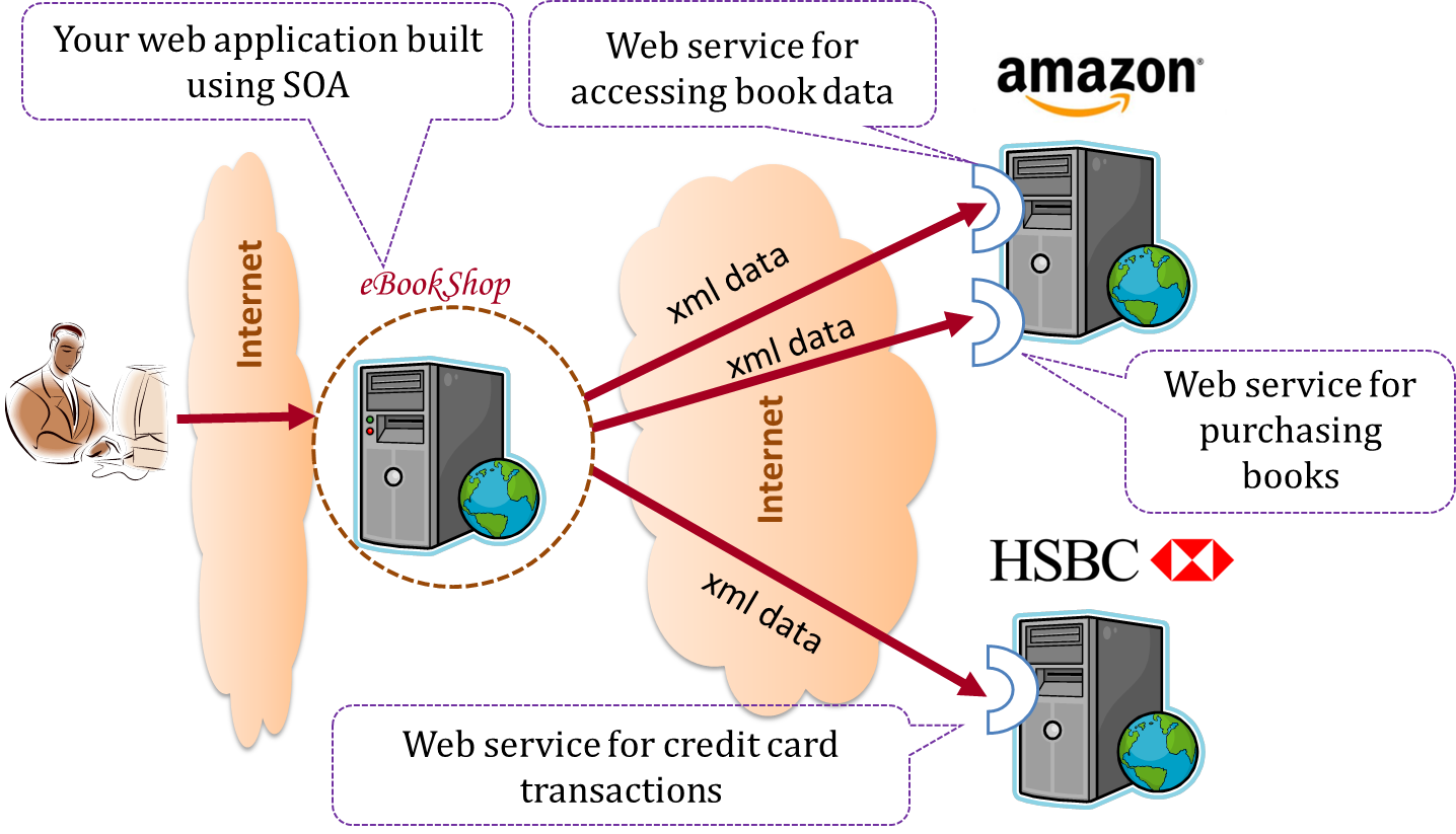
Event-driven Architectural Style
Event-driven style controls the flow of the application by detecting from event emitters and communicating those events to interested event consumers. This architectural style is often used in GUIs.
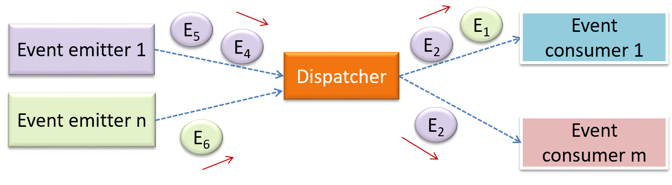
When the ‘button clicked’ event occurs in a GUI, that event can be transmitted to components that are interested in reacting to that event. Similarly, events detected at a printer port can be transmitted to components related to operating the printer. The same event can be sent to multiple consumers too.
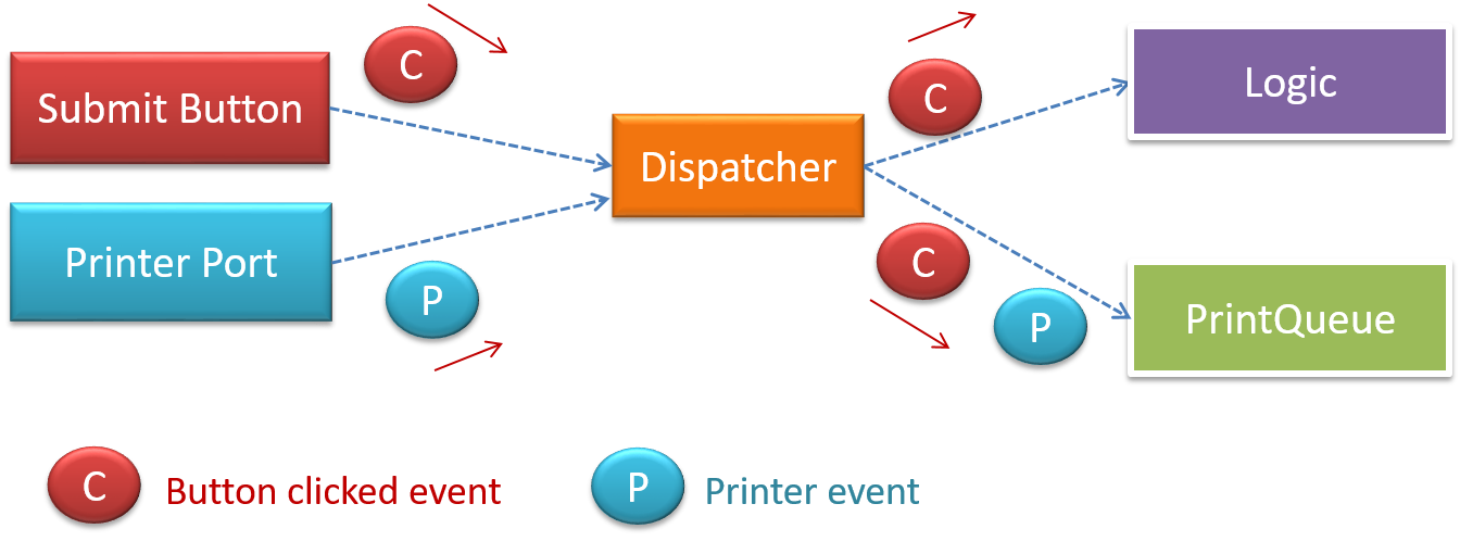
More
Other well-known architectural styles include the pipes-and-filters architecture, the broker architecture, the peer-to-peer architecture, and the message-oriented architecture.
Software Design Patterns
Introduction
Design pattern: An elegant reusable solution to a commonly recurring problem within a given context in software design.
In software development, there are certain problems that recur in a certain context.
Some examples of recurring design problems:
| Design Context | Recurring Problem |
|---|---|
| Assembling a system that makes use of other existing systems implemented using different technologies | What is the best architecture? |
| UI needs to be updated when the data in the application backend changes | How to initiate an update to the UI when data changes without coupling the backend to the UI? |
After repeated attempts at solving such problems, better solutions are discovered and refined over time. These solutions are known as design patterns, a term popularized by the seminal book Design Patterns: Elements of Reusable Object-Oriented Software by the so-called "Gang of Four" (GoF) written by Erich Gamma, Richard Helm, Ralph Johnson, and John Vlissides.
The common format to describe a pattern consists of the following components:
- Context: The situation or scenario where the design problem is encountered.
- Problem: The main difficulty to be resolved.
- Solution: The core of the solution. It is important to note that the solution presented only includes the most general details, which may need further refinement for a specific context.
- Anti-patterns (optional): Commonly used solutions, which are usually incorrect and/or inferior to the Design Pattern.
- Consequences (optional): Identifying the pros and cons of applying the pattern.
- Other useful information (optional): Code examples, known uses, other related patterns, etc.
Singleton Pattern
Context
Certain classes should have no more than just one instance (e.g. the main controller class of the system). These single instances are commonly known as singletons.
Problem
A normal class can be instantiated multiple times by invoking the constructor.
Solution
Make the constructor of the singleton class private, because a public constructor will allow others to instantiate the class at will. Provide a public class-level method to access the single instance.
Example:
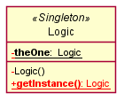
The <<Singleton>> in the class above uses the UML stereotype notation, which is used to (optionally) indicate the purpose or the role played by a UML element. In this example, the class Logic is playing the role of a Singleton class. The general format is <<role/purpose>>.
Here is the typical implementation of how the Singleton pattern is applied to a class:
class Logic {
    private static Logic theOne = null;

    private Logic() {
        ...
    }

    public static Logic getInstance() {
        if (theOne == null) {
            theOne = new Logic();
        }
        return theOne;
    }
}
Notes:
- The constructor is
private, which prevents instantiation from outside the class. - The single instance of the singleton class is maintained by a
privateclass-level variable. - Access to this object is provided by a
publicclass-level operationgetInstance()which instantiates a single copy of the singleton class when it is executed for the first time. Subsequent calls to this operation return the single instance of the class.
If Logic was not a Singleton class, a Logic object can be created as follows:
Logic m = new Logic();
But when it is a Singleton class, the single Logic object needs to be accessed as follows:
Logic m = Logic.getInstance();
Pros:
- easy to apply
- effective in achieving its goal with minimal extra work
- provides an easy way to access the singleton object from anywhere in the codebase
Cons:
- The singleton object acts like a global variable that increases coupling across the codebase.
- In testing, it is difficult to replace Singleton objects with stubs (static methods cannot be overridden).
- In testing, singleton objects carry data from one test to another even when you want each test to be independent of the others.
Given that there are some significant cons, it is recommended that you apply the Singleton pattern when, in addition to requiring only one instance of a class, there is a risk of creating multiple objects by mistake, and creating such multiple objects has real negative consequences.
Abstraction Occurrence Pattern
Context
There is a group of similar entities that appear to be ‘occurrences’ (or ‘copies’) of the same thing, sharing lots of common information, but also differing in significant ways.
In a library, there can be multiple copies of the same book title. Each copy shares common information such as book title, author, ISBN, etc. However, there are also significant differences like purchase date and barcode number (assumed to be unique for each copy of the book).
Other examples:
- Episodes of the same TV series
- Stock items of the same product model (e.g. TV sets of the same model)
Problem
Representing the objects mentioned previously as a single class would be problematic because it results in duplication of data which can lead to inconsistencies in data (if some of the duplicates are not updated consistently).
Take for example the problem of representing books in a library. Assume that there could be multiple copies of the same title, bearing the same ISBN number, but different serial numbers.
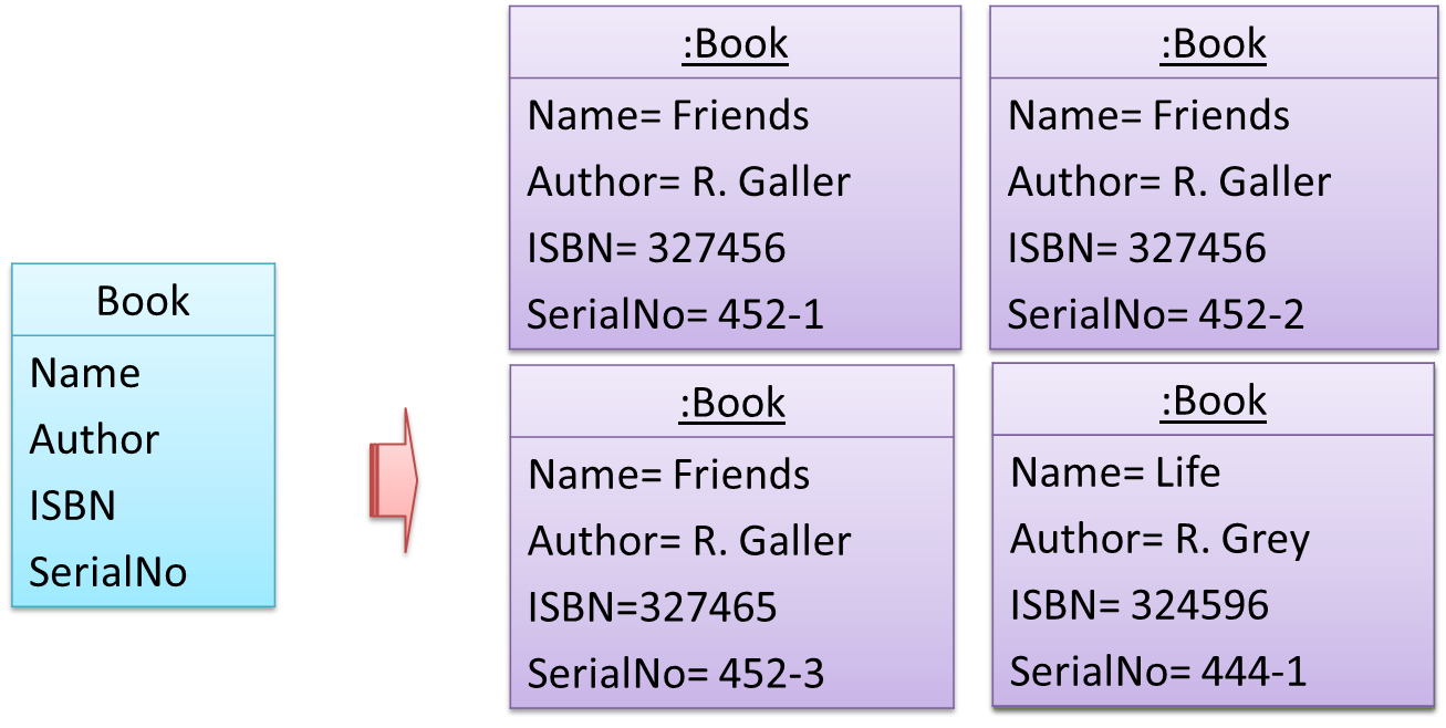
The above solution requires common information to be duplicated by all instances. This will not only waste storage space, but also creates a consistency problem. Suppose that after creating several copies of the same title, the librarian realized that the author name was wrongly spelt. To correct this mistake, the system needs to go through every copy of the same title to make the correction. Also, if a new copy of the title is added later on, the librarian (or the system) has to make sure that all information entered is the same as the existing copies to avoid inconsistency.
Anti-pattern
Refer to the same Library example given above.
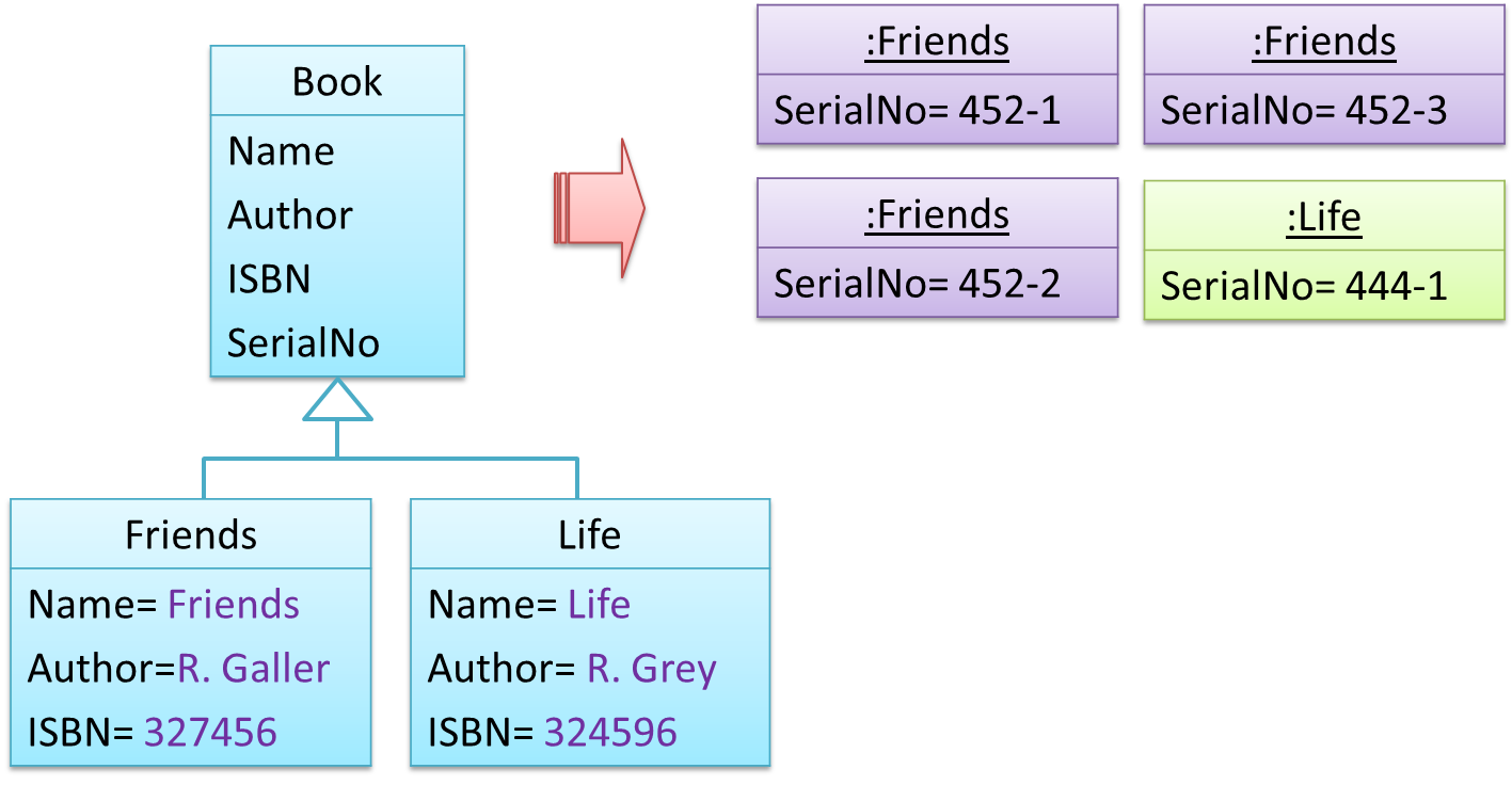
The design above segregates the common and unique information into a class hierarchy. Each book title is represented by a separate class with common data (i.e., Name, Author, ISBN) hard-coded in the class itself. This solution is problematic because each book title is represented as a class, resulting in thousands of classes (one for each title). Every time the library buys new books, the source code of the system will have to be updated with new classes.
Solution
Let a copy of an entity (e.g. a copy of a book) be represented by two objects instead of one, separating the common and unique information into two classes to avoid duplication.
Given below is how the pattern is applied to the Library example:
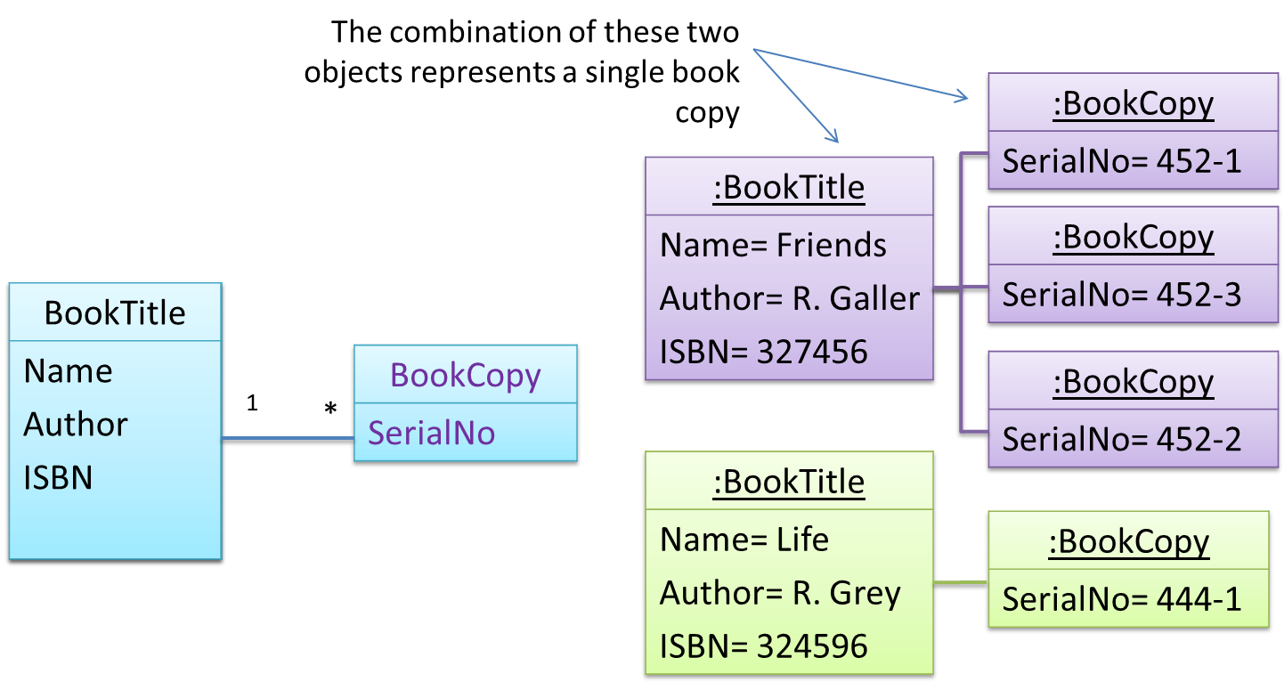
Here's a more generic example:
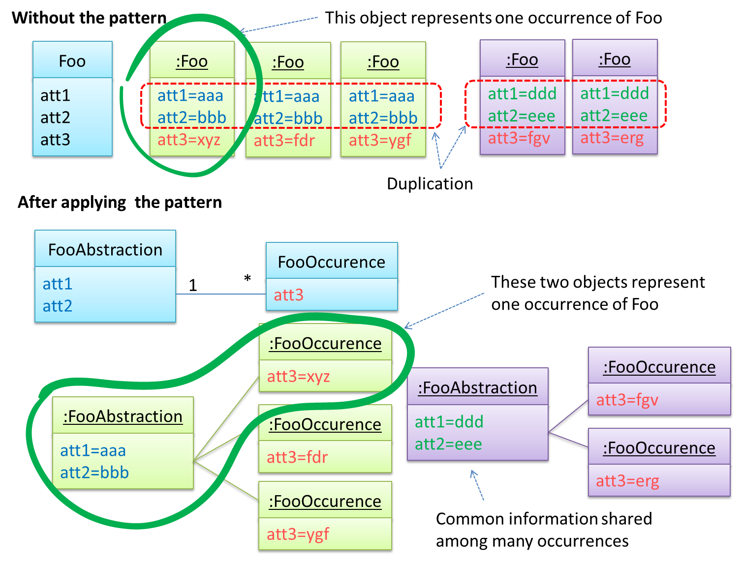
The general solution:

The <<Abstraction>> class should hold all common information, and the unique information should be kept by the <<Occurrence>> class. Note that ‘Abstraction’ and ‘Occurrence’ are not class names, but roles played by each class. Think of this diagram as a meta-model (i.e., a ‘model of a model’) of the BookTitle-BookCopy class diagram given above.
Facade Pattern
Context
Components need to access functionality deep inside other components.
The UI component of a Library system might want to access functionality of the Book class contained inside the Logic component.
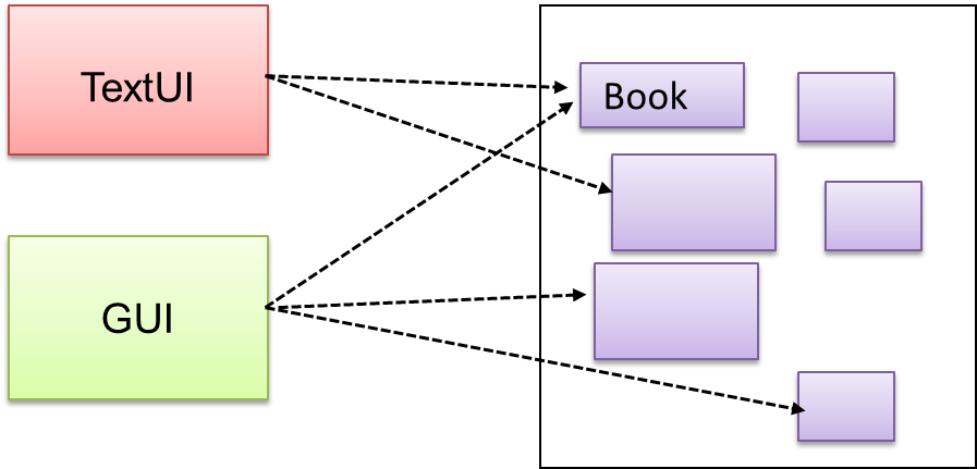
Problem
Access to the component should be allowed without exposing its internal details. e.g. the UI component should access the functionality of the Logic component without knowing that it contains a Book class within it.
Solution
Include a class that sits between the component internals and users of the component such that all access to the component happens through the Facade class.
The following class diagram applies the Facade pattern to the Library System example. The LibraryLogic class is the Facade class.
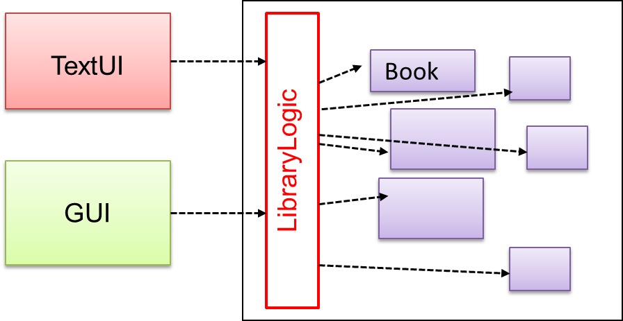
Command Pattern
Context
A system is required to execute a number of commands, each doing a different task. For example, a system might have to support Sort, List, Reset commands.
Problem
It is preferable that some part of the code executes these commands without having to know each command type. e.g., there can be a CommandQueue object that is responsible for queuing commands and executing them without knowledge of what each command does.
Solution
The essential element of this pattern is to have a general <<Command>> object that can be passed around, stored, executed, etc without knowing the type of command (i.e., via polymorphism).
Let us examine an example application of the pattern first:
In the example solution below, the CommandCreator creates List, Sort, and Reset Command objects and adds them to the CommandQueue object. The CommandQueue object treats them all as Command objects and performs the execute/undo operation on each of them without knowledge of the specific Command type. When executed, each Command object will access the DataStore object to carry out its task. The Command class can also be an abstract class or an interface.
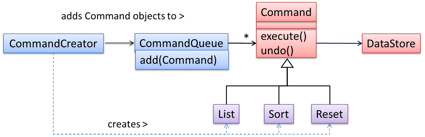
The general form of the solution is as follows.
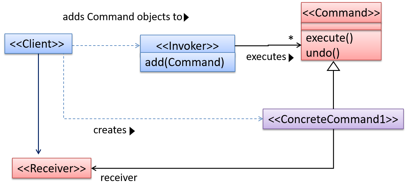
The <<Client>> creates a <<ConcreteCommand>> object, and passes it to the <<Invoker>>. The <<Invoker>> object treats all commands as a general <<Command>> type. <<Invoker>> issues a request by calling execute() on the command. If a command is undoable, <<ConcreteCommand>> will store the state for undoing the command prior to invoking execute(). In addition, the <<ConcreteCommand>> object may have to be linked to any <<Receiver>> of the command () before it is passed to the <<Invoker>>. Note that an application of the command pattern does not have to follow the structure given above.
Model View Controller (MVC) Pattern
Context
Most applications support storage/retrieval of information, displaying of information to the user (often via multiple UIs having different formats), and changing stored information based on external inputs.
Problem
The high coupling that can result from the interlinked nature of the features described above.
Solution
Decouple data, presentation, and control logic of an application by separating them into three different components: Model, View and Controller.
- View: Displays data, interacts with the user, and pulls data from the model if necessary.
- Controller: Detects UI events such as mouse clicks and button pushes, and takes follow up action. Updates/changes the model/view when necessary.
- Model: Stores and maintains data. Updates the view if necessary.
The relationship between the components can be observed in the diagram below. Typically, the UI is the combination of View and Controller.
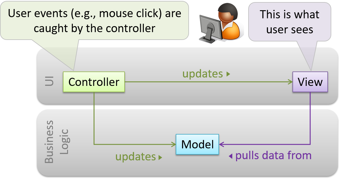
Given below is a concrete example of MVC applied to a student management system. In this scenario, the user is retrieving the data of a student.
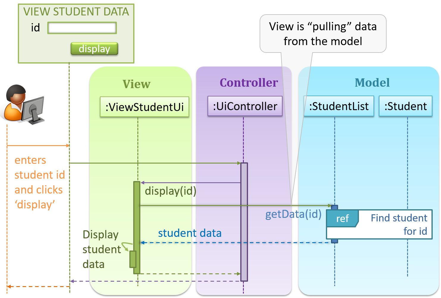
In the diagram above, when the user clicks on a button using the UI, the ‘click’ event is caught and handled by the UiController. The ref frame indicates that the interactions within that frame have been extracted out to another separate sequence diagram.
Note that in a simple UI where there’s only one view, Controller and View can be combined as one class.
There are many variations of the MVC model used in different domains. For example, the one used in a desktop GUI could be different from the one used in a web application.
Observer Pattern
Context
An object (possibly more than one) is interested in being notified when a change happens to another object. That is, some objects want to ‘observe’ another object.
Consider this scenario from a student management system where the user is adding a new student to the system.
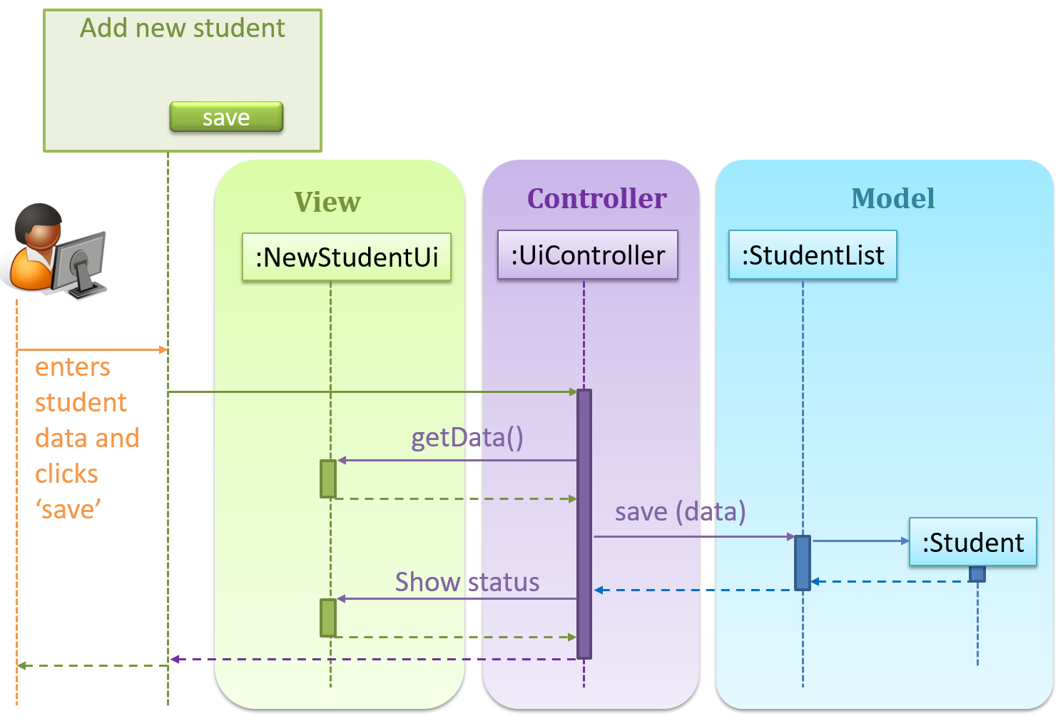
Now, assume the system has two additional views used in parallel by different users:
StudentListUi: that accesses a list of students andStudentStatsUi: that generates statistics of current students.
When a student is added to the database using NewStudentUi shown above, both StudentListUi and StudentStatsUi should get updated automatically, as shown below.
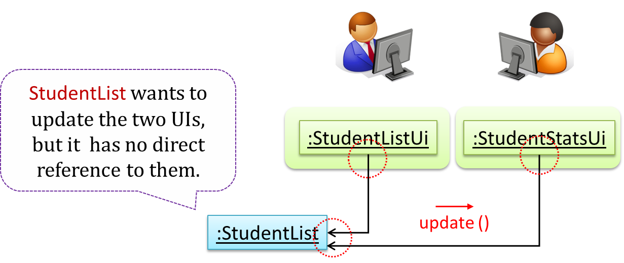
However, the StudentList object has no knowledge about StudentListUi and StudentStatsUi (note the direction of the navigability) and has no way to inform those objects. This is an example of the type of problem addressed by the Observer pattern.
Problem
The ‘observed’ object does not want to be coupled to objects that are ‘observing’ it.
Solution
Force the communication through an interface known to both parties.
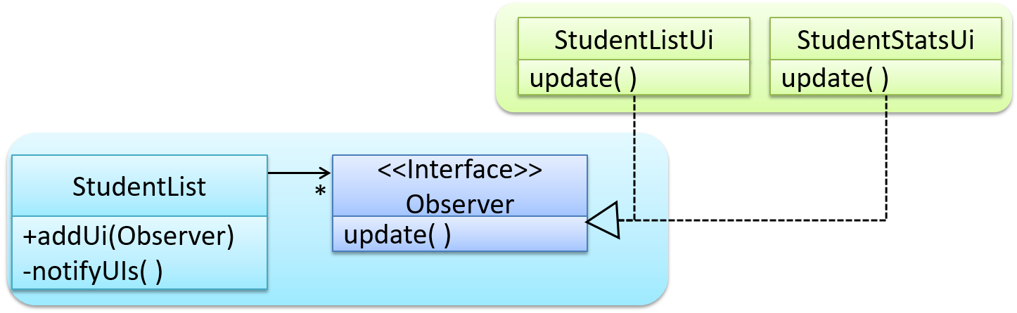
Here is the Observer pattern applied to the student management system.
During the initialization of the system,
First, create the relevant objects.
StudentList studentList = new StudentList();
StudentListUi listUi = new StudentListUi();
StudentStatsUi statsUi = new StudentStatsUi();
Next, the two UIs indicate to the
StudentListthat they are interested in being updated wheneverStudentListchanges. This is also known as ‘subscribing for updates’.studentList.addUi(listUi); studentList.addUi(statsUi);Within the
addUioperation ofStudentList, all Observer object subscribers are added to an internal data structure calledobserverList.// StudentList class public void addUi(Observer o) { observerList.add(o); }
Now, whenever the data in StudentList changes (e.g. when a new student is added to the StudentList),
All interested observers are updated by calling the
notifyUIsoperation.// StudentList class public void notifyUIs() { // for each observer in the list for (Observer o: observerList) { o.update(); } }UIs can then pull data from the
StudentListwhenever theupdateoperation is called.// StudentListUI class public void update() { // refresh UI by pulling data from StudentList }Note that
StudentListis unaware of the exact nature of the two UIs but still manages to communicate with them via an intermediary.
Here is the generic description of the observer pattern:
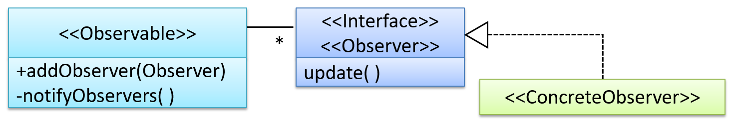
<<Observer>>is an interface: any class that implements it can observe an<<Observable>>. Any number of<<Observer>>objects can observe (i.e., listen to changes of) the<<Observable>>object.- The
<<Observable>>maintains a list of<<Observer>>objects.addObserver(Observer)operation adds a new<<Observer>>to the list of<<Observer>>s. - Whenever there is a change in the
<<Observable>>, thenotifyObservers()operation is called that will call theupdate()operation of all<<Observer>>s in the list.
In a GUI application, how is the Controller notified when the “save” button is clicked? UI frameworks such as JavaFX have inbuilt support for the Observer pattern.
More
Design patterns are usually embedded in a larger design and sometimes applied in combination with other design patterns.
Let us look at a case study that shows how design patterns are used in the design of a class structure for a Stock Inventory System (SIS) for a shop. The shop sells appliances and accessories for the appliances. SIS simply stores information about each item in the store.
Use Cases:
- Create a new item
- View information about an item
- Modify information about an item
- View all available accessories for a given appliance
- List all items in the store
SIS can be accessed using multiple terminals. Shop assistants use their own terminals to access SIS, while the shop manager’s terminal continuously displays a list of all items in the store. In the future, it is expected that suppliers of items use their own applications to connect to SIS to get real-time information about the current stock status. User authentication is not required for the current version, but may be required in the future.
A step by step explanation of the design is given below. Note that this is one out of many possible designs. Design patterns are also applied where appropriate.
A StockItem can be an Appliance or an Accessory.
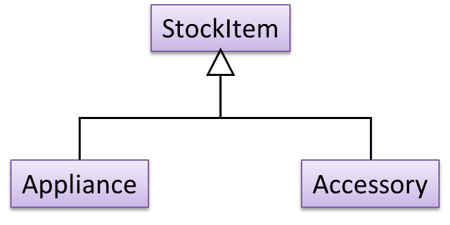
To track that each Accessory is associated with the correct Appliance, consider the following alternative class structures.
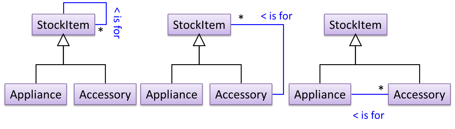
The third one seems more appropriate (the second one is suitable if accessories can have accessories). Next, consider between keeping a list of Appliances, and a list of StockItems. Which is more appropriate?
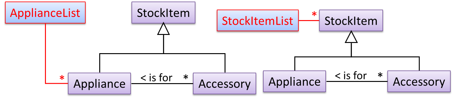
The latter seems more suitable because it can handle both appliances and accessories the same way. Next, an abstraction occurrence pattern is applied to keep track of StockItems.
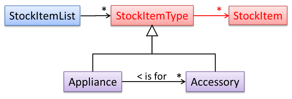
Note the inclusion of navigabilities. Here’s a sample object diagram based on the class model created thus far.
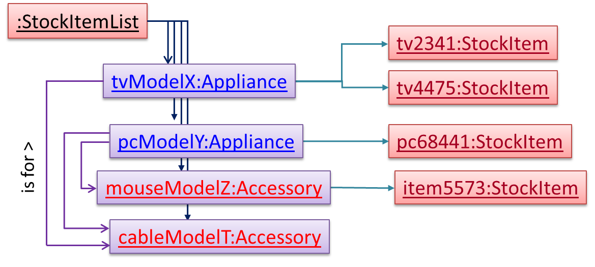
Next, apply the façade pattern to shield the SIS internals from the UI.
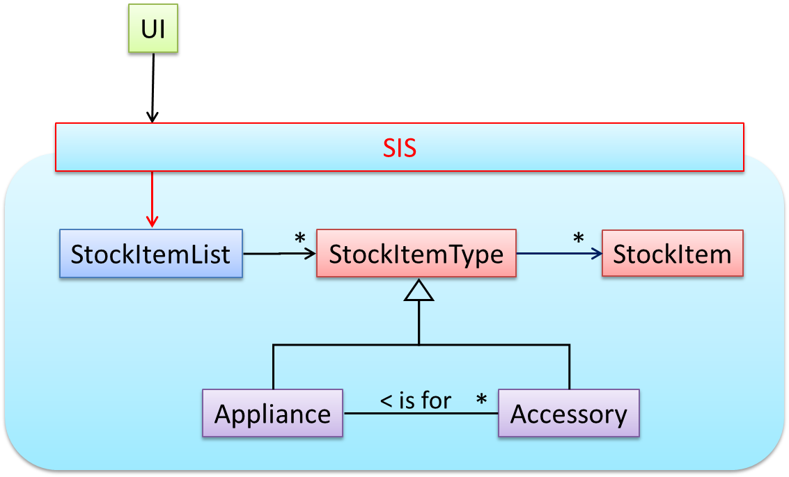
As UI consists of multiple views, the MVC pattern is applied here.
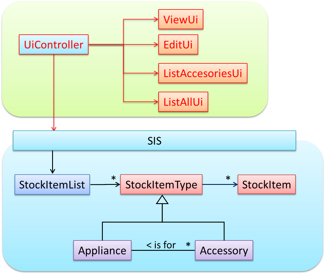
Some views need to be updated when the data changes; apply the Observer pattern here.
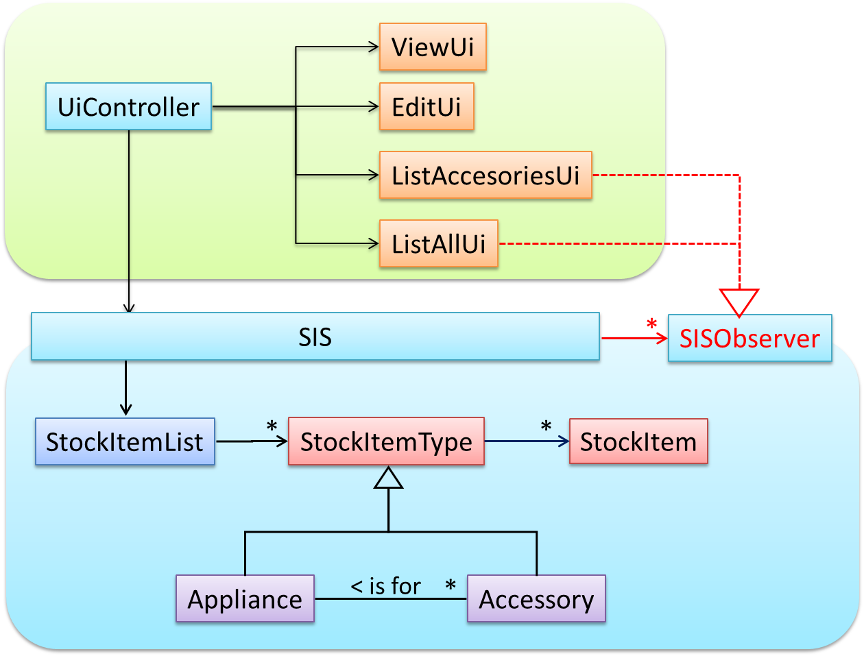
In addition, the Singleton pattern can be applied to the façade class.
The most famous source of design patterns is the "Gang of Four" (GoF) book which contains 23 design patterns divided into three categories:
- Creational: About object creation. They separate the operation of an application from how its objects are created.
- Abstract Factory, Builder, Factory Method, Prototype, Singleton
- Structural: About the composition of objects into larger structures while catering for future extension in structure.
- Adapter, Bridge, Composite, Decorator, Façade, Flyweight, Proxy
- Behavioral: Defining how objects interact and how responsibility is distributed among them.
- Chain of Responsibility, Command, Interpreter, Template Method, Iterator, Mediator, Memento, Observer, State, Strategy, Visitor
Design patterns provide a high-level vocabulary to talk about design.
Someone can say 'apply Observer pattern here' instead of having to describe the mechanics of the solution in detail.
Knowing more patterns is a way to become more ‘experienced’. Aim to learn at least the context and the problem of patterns so that when you encounter those problems you know where to look for a solution.
Some patterns are domain-specific e.g. patterns for distributed applications, some are created in-house e.g. patterns in the company/project and some can be self-created e.g. from past experience.
Be careful not to overuse patterns. Do not throw patterns at a problem at every opportunity. Patterns come with overhead such as adding more classes or increasing the levels of abstraction. Use them only when they are needed. Before applying a pattern, make sure that:
- there is substantial improvement in the design, not just superficial.
- the associated tradeoffs are carefully considered. There are times when a design pattern is not appropriate (or an overkill).
The notion of capturing design ideas as "patterns" is usually attributed to Christopher Alexander. He is a building architect noted for his theories about design. His book The Timeless Way of Building talks about "design patterns" for constructing buildings.
Here is a sample pattern from that book:
When a room has a window with a view, the window becomes a focal point: people are attracted to the window and want to look through it. The furniture in the room creates a second focal point: everyone is attracted toward whatever point the furniture aims them at (usually the center of the room or a TV). This makes people feel uncomfortable. They want to look out the window, and toward the other focus at the same time. If you rearrange the furniture, so that its focal point becomes the window, then everyone will suddenly notice that the room is much more “comfortable”.
Apparently, patterns and anti-patterns are found in the field of building architecture. This is because they are general concepts applicable to any domain, not just software design. In software engineering, there are many general types of patterns: Analysis patterns, Design patterns, Testing patterns, Architectural patterns, Project management patterns, and so on.
In fact, the abstraction occurrence pattern is more of an analysis pattern than a design pattern, while MVC is more of an architectural pattern.
New patterns can be created too. If a common problem that needs to be solved frequently leads to a non-obvious and better solution, it can be formulated as a pattern so that it can be reused by others. However, don’t reinvent the wheel; the pattern might already exist.
Design Approaches
In a smaller system, the design of the entire system can be shown in one place.
This class diagram of se-edu/addressbook-level2 depicts the design of the entire software.
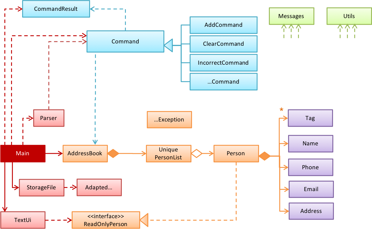
The design of bigger systems needs to be done/shown at multiple levels.
This architecture diagram of se-edu/addressbook-level3 depicts the high-level design of the software.
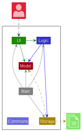
Here are examples of lower level designs of some components of the same software:
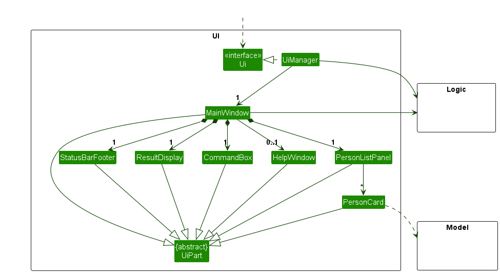
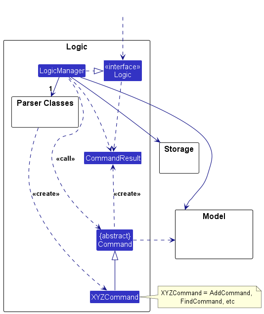
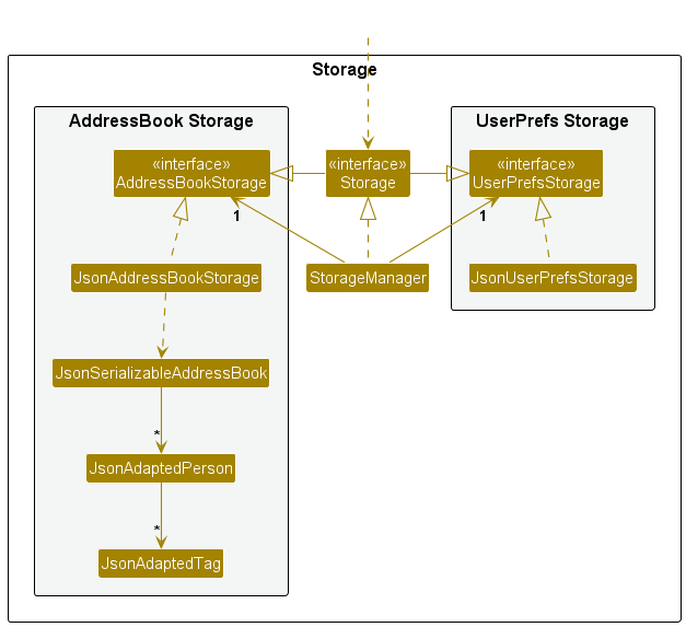
Multi-level design can be done in a top-down manner, bottom-up manner, or as a mix.
- Top-down: Design the high-level design first and flesh out the lower levels later. This is especially useful when designing big and novel systems where the high-level design needs to be stable before lower levels can be designed.
- Bottom-up: Design lower level components first and put them together to create the higher-level systems later. This is not usually scalable for bigger systems. One instance where this approach might work is when designing a variation of an existing system or re-purposing existing components to build a new system.
- Mix: Design the top levels using the top-down approach but switch to a bottom-up approach when designing the bottom levels.
Agile design can be contrasted with full upfront design in the following way:
Agile designs are emergent, they’re not defined up front. Your overall system design will emerge over time, evolving to fulfill new requirements and take advantage of new technologies as appropriate. Although you will often do some initial architectural modeling at the very beginning of a project, this will be just enough to get your team going. This approach does not produce a fully documented set of models in place before you may begin coding. -- adapted from agilemodeling.com
SECTION: IMPLEMENTATION
IDEs
Introduction
Professional software engineers often write code using Integrated Development Environments (IDEs). IDEs support most development-related work within the same tool (hence, the term integrated).
An IDE generally consists of:
- A source code editor that includes features such as syntax coloring, auto-completion, easy code navigation, error highlighting, and code-snippet generation.
- A compiler and/or an interpreter (together with other build automation support) that facilitates the compilation/linking/running/deployment of a program.
- A debugger that allows the developer to execute the program one step at a time to observe the run-time behavior in order to locate bugs.
- Other tools that aid various aspects of coding e.g., support for automated testing, drag-and-drop construction of UI components, version management support, simulation of the target runtime platform, modeling support, AI-assisted coding help, collaborative coding with others.
Examples of popular IDEs:
- Java: Eclipse, IntelliJ IDEA, NetBeans
- C#, C++: Visual Studio
- Swift: XCode
- Python: PyCharm
- Multiple languages: VS Code
Some web-based IDEs have appeared in recent times too e.g., Amazon's Cloud9 IDE.
Some experienced developers, in particular those with a UNIX background, prefer lightweight yet powerful text editors with scripting capabilities (e.g., Emacs) over heavier IDEs.
Debugging
Debugging is the process of discovering defects in the program. Here are some approaches to debugging:
- Bad -- By inserting temporary print statements: This is an ad-hoc approach in which print statements are inserted in the program to print information relevant to debugging, such as variable values. e.g.,
Exiting process() method, x is 5.347. This approach is not recommended due to these reasons:- Incurs extra effort when inserting and removing the print statements.
- These extraneous program modifications increase the risk of introducing errors into the program.
- These print statements, if not removed promptly after the debugging, may even appear unexpectedly in the production version.
- Bad -- By manually tracing through the code: Otherwise known as ‘eye-balling’, this approach doesn't have the cons of the previous approach, but it too is not recommended (other than as a 'quick try') due to these reasons:
- It is a difficult, time consuming, and error-prone technique.
- If you didn't spot the error while writing the code, you might not spot the error when reading the code either.
- Good -- Using a debugger: A debugger tool allows you to pause the execution, then step through the code one statement at a time while examining the internal state if necessary. Most IDEs come with an inbuilt debugger. This is the recommended approach for debugging.
Code Quality
Introduction
Always code as if the person who ends up maintaining your code will be a violent psychopath who knows where you live. -- Martin Golding
Production code needs to be of high quality. Given how the world is becoming increasingly dependent on software, poor quality code is something no one can afford to tolerate.
Guideline: Maximize Readability
Programs should be written and polished until they acquire publication quality. --Niklaus Wirth
Among various dimensions of code quality, such as run-time efficiency, security, and robustness, one of the most important is readability (aka understandability). This is because in any non-trivial software project, code needs to be read, understood, and modified by other developers later on. Even if you do not intend to pass the code to someone else, code quality is still important because you will become a 'stranger' to your own code someday.
If you need more than 3 levels of indentation, you're screwed anyway, and should fix your program. --Linux 1.3.53 Coding Style
Avoid deep nesting -- the deeper the nesting, the harder it is for the reader to keep track of the logic.
In particular, avoid arrowhead style code.
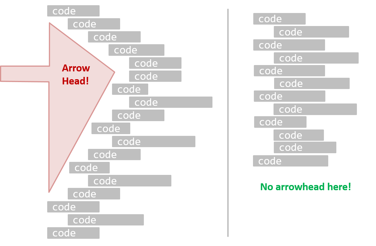
A real code example:
Bad | |
Good | |
Bad | | Good |
Guideline: Follow a Standard
One essential way to improve code quality is to follow a consistent style. That is why software engineers usually follow a strict coding standard (aka style guide).
The aim of a coding standard is to make the entire codebase look like it was written by one person. A coding standard is usually specific to a programming language and specifies guidelines such as the locations of opening and closing braces, indentation styles and naming styles (e.g., whether to use Hungarian style, Pascal casing, Camel casing, etc.). It is important that the whole team/company uses the same coding standard and that the standard is generally not inconsistent with typical industry practices. If a company's coding standard is very different from what is typically used in the industry, new recruits will take longer to get used to the company's coding style.
IDEs can help to enforce some parts of a coding standard e.g., indentation rules.
Go through the Java coding standard at @SE-EDU and learn the basic style rules.
Sample coding standard: PEP 8 Python Style Guide -- by Python.org
Go through the Java coding standard at @SE-EDU and learn the intermediate style rules.
Guideline: Name Well
Proper naming improves the readability of code. It also reduces bugs caused by ambiguities regarding the intent of a variable or a method.
There are only two hard things in Computer Science: cache invalidation and naming things. -- Phil Karlton
Guideline: Avoid Unsafe Shortcuts
It is safer to use language constructs in the way they are meant to be used, even if the language allows shortcuts. Such coding practices are common sources of bugs. Know them and avoid them.
Guideline: Comment Minimally, But Sufficiently
Good code is its own best documentation. As you’re about to add a comment, ask yourself, ‘How can I improve the code so that this comment isn’t needed?’ Improve the code and then document it to make it even clearer. -- Steve McConnell, Author of Clean Code
Some think commenting heavily increases the 'code quality'. That is not so. Avoid writing comments to explain bad code. Improve the code to make it self-explanatory.
Refactoring
The process of restructuring code in small steps without modifying its external behavior is called refactoring. Refactoring is needed because the first version of the code you write may not be of production quality. It is OK to first concentrate on making the code work, rather than worry over the quality of the code, as long as you improve the quality later.
- Refactoring is not rewriting: Discarding poorly-written code entirely and re-writing it from scratch is not refactoring because refactoring needs to be done in small steps.
- Refactoring is not bug fixing: By definition, refactoring is different from bug fixing or any other modifications that alter the external behavior (e.g. adding a feature) of the component in concern.
Refactoring code can have many secondary benefits e.g.
- hidden bugs become easier to spot
- improve performance (sometimes, simpler code runs faster than complex code because simpler code is easier for the compiler to optimize).
Given below are two common refactorings (more).
Refactoring Name: Consolidate Duplicate Conditional Fragments
Situation: The same fragment of code is in all branches of a conditional expression.
Method: Move it outside of the expression.
Example:
| → | |
| → | |
Refactoring Name: Extract Method
Situation: You have a code fragment that can be grouped together.
Method: Turn the fragment into a method whose name explains the purpose of the method.
Example:
void printOwing() {
    printBanner();

    // print details
    System.out.println("name:    " + name);
    System.out.println("amount    " + getOutstanding());
}
void printOwing() {
    printBanner();
    printDetails(getOutstanding());
}

void printDetails(double outstanding) {
    System.out.println("name:    " + name);
    System.out.println("amount    " + outstanding);
}
def print_owing():
    print_banner()

    # print details
    print("name:    " + name)
    print("amount    " + get_outstanding())
def print_owing():
    print_banner()
    print_details(get_outstanding())

def print_details(amount):
    print("name:    " + name)
    print("amount    " + amount)
Some IDEs have builtin support for basic refactorings such as automatically renaming a variable/method/class in all places it has been used.
Refactoring, even if done with the aid of an IDE, may still result in regressions. Therefore, each small refactoring should be followed by regression testing.
There are refactoring catalogs listing various refactorings. Given below are some commonly used refactorings.
One way to identify refactoring opportunities is by code smells.
A code smell is a surface indication that usually corresponds to a deeper problem in the system. First, a smell is by definition something that's quick to spot. Second, smells don't always indicate a problem.
--adapted from https://martinfowler.com/bliki/CodeSmell.html
An example (from the same source as above) is the code smell data class i.e., a class with all data and no behavior. When you encounter the such a class, you can explore if refactoring it to move the corresponding behavior into that class is appropriate. Some more examples:
Periodic refactoring is a good way to pay off the technical debt a codebase has accumulated.
Software systems are prone to the build up of cruft - deficiencies in internal quality that make it harder than it would ideally be to modify and extend the system further. Technical Debt is a metaphor, coined by Ward Cunningham, that frames how to think about dealing with this cruft, thinking of it like a financial debt. The extra effort that it takes to add new features is the interest paid on the debt.
--https://martinfowler.com/bliki/TechnicalDebt.html
While it is important to refactor frequently so as to avoid the accumulation of ‘messy’ code (aka technical debt), an important question is how much refactoring is too much refactoring? It is too much refactoring when the benefits no longer justify the cost. The costs and the benefits depend on the context. That is why some refactorings are ‘opposites’ of each other (e.g., extract method vs inline method).
Documentation
Introduction
Developer-to-developer documentation can be in one of two forms:
- Documentation for developer-as-user: Software components are written by developers and reused by other developers, which means there is a need to document how such components are to be used. Such documentation can take several forms:
- API documentation: APIs expose functionality in small-sized, independent and easy-to-use chunks, each of which can be documented systematically.
- Tutorial-style instructional documentation: In addition to explaining functions/methods independently, some higher-level explanations of how to use an API can be useful.
- Example of API Documentation: String API.
- Example of tutorial-style documentation: Java Internationalization Tutorial.
- Example of API Documentation: string API.
- Example of tutorial-style documentation: How to use Regular Expressions in Python
- Documentation for developer-as-maintainer: There is a need to document how a system or a component is designed, implemented and tested so that other developers can maintain and evolve the code. Writing documentation of this type is harder because of the need to explain complex internal details. However, given that readers of this type of documentation usually have access to the source code itself, only some information needs to be included in the documentation, as code (and code comments) can also serve as a complementary source of information.
- An example: se-edu/addressbook-level4 Developer Guide.
Another view proposed by Daniele Procida in this article is as follows:
There is a secret that needs to be understood in order to write good software documentation: there isn’t one thing called documentation, there are four. They are: tutorials, how-to guides, explanation and technical reference. They represent four different purposes or functions, and require four different approaches to their creation. Understanding the implications of this will help improve most software documentation - often immensely. ...
TUTORIALS
A tutorial:
- is learning-oriented
- allows the newcomer to get started
- is a lesson
Analogy: teaching a small child how to cook
HOW-TO GUIDES
A how-to guide:
- is goal-oriented
- shows how to solve a specific problem
- is a series of steps
Analogy: a recipe in a cookery book
EXPLANATION
An explanation:
- is understanding-oriented
- explains
- provides background and context
Analogy: an article on culinary social history
REFERENCE
A reference guide:
- is information-oriented
- describes the machinery
- is accurate and complete
Analogy: a reference encyclopedia article
Software documentation (applies to both user-facing and developer-facing) is best kept in a text format for ease of version tracking. A writer-friendly source format is also desirable as non-programmers (e.g., technical writers) may need to author/edit such documents. As a result, formats such as Markdown, AsciiDoc, and PlantUML are often used for software documentation.
Guidelines
Guideline: Go Top-down, Not Bottom-up
When writing project documents, a top-down breadth-first explanation is easier to understand than a bottom-up one.
The main advantage of the top-down approach is that the document is structured like an upside down tree (root at the top) and the reader can travel down a path she is interested in until she reaches the component she is interested to learn in-depth, without having to read the entire document or understand the whole system.
To explain a system called SystemFoo with two sub-systems, FrontEnd and BackEnd, start by describing the system at the highest level of abstraction, and progressively drill down to lower level details. An outline for such a description is given below.
[First, explain what the system is, in a black-box fashion (no internal details, only the external view).]
SystemFoois a ....
[Next, explain the high-level architecture of SystemFoo, referring to its major components only.]
SystemFooconsists of two major components:FrontEndandBackEnd.
The job ofFrontEndis to ... while the job ofBackEndis to ...
And this is howFrontEndandBackEndwork together ...
[Now you can drill down to FrontEnd's details.]
FrontEndconsists of three major components:A,B,C
A's job is to ...B's job is to...C's job is to...
And this is how the three components work together ...
[At this point, further drill down to the internal workings of each component. A reader who is not interested in knowing the nitty-gritty details can skip ahead to the section on BackEnd.]
In-depth description of
A
In-depth description ofB
...
[At this point drill down to the details of the BackEnd.]
...
Guideline: Aim for Comprehensibility
Technical documents exist to help others understand technical details. Therefore, it is not enough for the documentation to be accurate and comprehensive; it should also be comprehensible.
Here are some tips on writing effective documentation.
- Use plenty of diagrams: It is not enough to explain something in words; complement it with visual illustrations (e.g. a UML diagram).
- Use plenty of examples: When explaining algorithms, show a running example to illustrate each step of the algorithm, in parallel to worded explanations.
- Use simple and direct explanations: Convoluted explanations and fancy words will annoy readers. Avoid long sentences.
- Get rid of statements that do not add value: For example, 'We made sure our system works perfectly' (who didn't?), 'Component X has its own responsibilities' (of course it has!).
- It is not a good idea to have separate sections for each type of artifact, such as 'use cases', 'sequence diagrams', 'activity diagrams', etc. Such a structure, coupled with the indiscriminate inclusion of diagrams without justifying their need, indicates a failure to understand the purpose of documentation. Include diagrams when they are needed to explain something. If you want to provide additional diagrams for completeness' sake, include them in the appendix as a reference.
Guideline: Document Minimally, but Sufficiently
Aim for 'just enough' developer documentation.
- Writing and maintaining developer documents is an overhead. You should try to minimize that overhead.
- If the readers are developers who will eventually read the code, the documentation should complement the code and should provide only just enough guidance to get started.
Anything that is already clear in the code need not be described in words. Instead, focus on providing higher level information that is not readily visible in the code or comments.
Refrain from duplicating chunks of text. When describing several similar algorithms/designs/APIs, etc., do not simply duplicate large chunks of text. Instead, describe the similarities in one place and emphasize only the differences in other places. It is very annoying to see pages and pages of similar text without any indication as to how they differ from each other.
Tools
JavaDoc
JavaDoc is a tool for generating API documentation in HTML format from comments in the source code. In addition, modern IDEs use JavaDoc comments to generate explanatory tooltips.
An example method header comment in JavaDoc format:
/**
 * Returns an Image object that can then be painted on the screen.
 * The url argument must specify an absolute {@link URL}. The name
 * argument is a specifier that is relative to the url argument.
 * <p>
 * This method always returns immediately, whether or not the
 * image exists. When this applet attempts to draw the image on
 * the screen, the data will be loaded. The graphics primitives
 * that draw the image will incrementally paint on the screen.
 *
 * @param url An absolute URL giving the base location of the image.
 * @param name The location of the image, relative to the url argument.
 * @return The Image at the specified URL.
 * @see Image
 */
public Image getImage(URL url, String name) {
    try {
        return getImage(new URL(url, name));
    } catch (MalformedURLException e) {
        return null;
    }
}
Generated HTML documentation:

Tooltip generated by IntelliJ IDE:
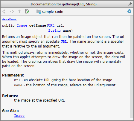
Markdown
AsciiDoc
AsciiDoc is similar to Markdown but has more powerful (and also more complex) syntax.
- AsciiDoc Writers Guide -- from Asciidoctor.org
Error Handling
Introduction
Well-written applications include error-handling code that allows them to recover gracefully from unexpected errors. When an error occurs, the application may need to request user intervention, or it may be able to recover on its own. In extreme cases, the application may log the user off or shut down the system. -- Microsoft
Exceptions
Exceptions are used to deal with 'unusual' but not entirely unexpected situations that the program might encounter at runtime.
Exception:
The term exception is shorthand for the phrase "exceptional event." An exception is an event, which occurs during the execution of a program, that disrupts the normal flow of the program's instructions. –- Java Tutorial (Oracle Inc.)
Examples:
- A network connection encounters a timeout due to a slow server.
- The code tries to read a file from the hard disk but the file is corrupted and cannot be read.
Most languages allow code that encountered an "exceptional" situation to encapsulate details of the situation in an Exception object and throw/raise that object so that another piece of code can catch it and deal with it. This is especially useful when the code that encountered the unusual situation does not know how to deal with it.
The extract below from the -- Java Tutorial (with slight adaptations) explains how exceptions are typically handled.
When an error occurs at some point in the execution, the code being executed creates an exception object and hands it off to the runtime system. The exception object contains information about the error, including its type and the state of the program when the error occurred. Creating an exception object and handing it to the runtime system is called throwing an exception.
After a method throws an exception, the runtime system attempts to find something to handle it in the . The runtime system searches the call stack for a method that contains a block of code that can handle the exception. This block of code is called an exception handler. The search begins with the method in which the error occurred and proceeds through the call stack in the reverse order in which the methods were called. When an appropriate handler is found, the runtime system passes the exception to the handler. An exception handler is considered appropriate if the type of the exception object thrown matches the type that can be handled by the handler.
The exception handler chosen is said to catch the exception. If the runtime system exhaustively searches all the methods on the call stack without finding an appropriate exception handler, the program terminates.
Advantages of exception handling in this way:
- The ability to propagate error information through the call stack.
- The separation of code that deals with 'unusual' situations from the code that does the 'usual' work.
In general, use exceptions only for 'unusual' conditions. Use normal return statements to pass control to the caller for conditions that are 'normal'.
Assertions
Assertions are used to define assumptions about the program state so that the runtime can verify them. An assertion failure indicates a possible bug in the code because the code has resulted in a program state that violates an assumption about how the code should behave.
An assertion can be used to express something like when the execution comes to this point, the variable v cannot be null.
If the runtime detects an assertion failure, it typically takes some drastic action such as terminating the execution with an error message. This is because an assertion failure indicates a possible bug and the sooner the execution stops, the safer it is.
In the Java code below, suppose you set an assertion that timeout returned by Config.getTimeout() is greater than 0. Now, if Config.getTimeout() returns -1 in a specific execution of this line, the runtime can detect it as an assertion failure -- i.e., an assumption about the expected behavior of the code turned out to be wrong which could potentially be the result of a bug -- and take some drastic action such as terminating the execution.
int timeout = Config.getTimeout();
// set assertion here ...
Use the assert keyword to define assertions.
This assertion will fail with the message x should be 0 if x is not 0 at this point.
x = getX();
assert x == 0 : "x should be 0";
...
Assertions can be disabled without modifying the code.
java -enableassertions HelloWorld (or java -ea HelloWorld) will run HelloWorld with assertions enabled while java -disableassertions HelloWorld will run it without verifying assertions.
Java disables assertions by default. This could create a situation where you think all assertions are being verified as true while in fact they are not being verified at all. Therefore, remember to enable assertions when you run the program if you want them to be in effect.
Enable assertions in IntelliJ (how?) and get an assertion to fail temporarily (e.g. insert an assert false into the code temporarily) to confirm assertions are being verified.
Java assert vs JUnit assertions: Both check for a given condition but JUnit assertions are more powerful and customized for testing. In addition, JUnit assertions are not disabled by default. Use JUnit assertions in test code and Java assert in functional code.
It is recommended that assertions be used liberally in the code. Their impact on performance is low, and worth the additional safety they provide.
Do not use assertions to do work because assertions can be disabled. If not, your program will stop working when assertions are not enabled.
The code below will not invoke the writeFile() method when assertions are disabled. If that method is performing some work that is necessary for your program, your program will not work correctly when assertions are disabled.
...
assert writeFile() : "File writing is supposed to return true";
Assertions are suitable for verifying assumptions about Internal Invariants, Control-Flow Invariants, Preconditions, Postconditions, and Class Invariants. Refer to Programming with Assertions (second half) to learn more.
Exceptions and assertions are two complementary ways of handling errors in software but they serve different purposes. Therefore, both assertions and exceptions should be used in code.
- The raising of an exception indicates an unusual condition created by the user (e.g. user inputs an unacceptable input) or the environment (e.g., a file needed for the program is missing).
- An assertion failure indicates the programmer made a mistake in the code (e.g., a null value is returned from a method that is not supposed to return null under any circumstances).
Logging
Logging is the deliberate recording of certain information during a program execution for future reference. Logs are typically written to a log file but it is also possible to log information in other ways e.g. into a database or a remote server.
Logging can be useful for troubleshooting problems. A good logging system records some system information regularly. When bad things happen to a system e.g. an unanticipated failure, their associated log files may provide indications of what went wrong and actions can then be taken to prevent it from happening again.
A log file is like the of an airplane; they don't prevent problems but they can be helpful in understanding what went wrong after the fact.

source: https://commons.wikimedia.org
Most programming environments come with logging systems that allow sophisticated forms of logging. They have features such as the ability to enable and disable logging easily or to change the logging .
This sample Java code uses Java’s default logging mechanism.
First, import the relevant Java package:
import java.util.logging.*;
Next, create a Logger:
private static Logger logger = Logger.getLogger("Foo");
Now, you can use the Logger object to log information. Note the use of a for each message. When running the code, the logging level can be set to WARNING so that log messages specified as having INFO level (which is a lower level than WARNING) will not be written to the log file at all.
// log a message at INFO level
logger.log(Level.INFO, "going to start processing");
// ...
processInput();
if (error) {
    // log a message at WARNING level
    logger.log(Level.WARNING, "processing error", ex);
}
// ...
logger.log(Level.INFO, "end of processing");
Defensive Programming
A defensive programmer codes under the assumption "if you leave room for things to go wrong, they will go wrong". Therefore, a defensive programmer proactively tries to eliminate any room for things to go wrong.
Consider a method MainApp#getConfig() that returns a Config object containing configuration data. A typical implementation is given below:
class MainApp {
    Config config;

    /** Returns the config object */
    Config getConfig() {
        return config;
    }
}
If the returned Config object is not meant to be modified, a defensive programmer might use a more defensive implementation given below. This is more defensive because even if the returned Config object is modified (although it is not meant to be), it will not affect the config object inside the MainApp object.
    /** Returns a copy of the config object */
    Config getConfig() {
        return config.copy(); // return a defensive copy
    }
Consider two classes, Account and Guarantor, with an association as shown in the following diagram:
Example:
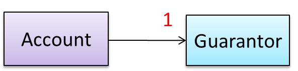
Here, the association is compulsory i.e., an Account object should always be linked to a Guarantor. One way to implement this is to simply use a reference variable, like this:
class Account {
    Guarantor guarantor;

    void setGuarantor(Guarantor g) {
        guarantor = g;
    }
}
However, what if someone else used the Account class like this?
Account a = new Account();
a.setGuarantor(null);
This results in an Account without a Guarantor! In a real banking system, this could have serious consequences! The code here did not try to prevent such a thing from happening. You can make the code more defensive by proactively enforcing the multiplicity constraint, like this:
class Account {
    private Guarantor guarantor;

    public Account(Guarantor g) {
        if (g == null) {
            stopSystemWithMessage(
                    "multiplicity violated. Null Guarantor");
        }
        guarantor = g;
    }
    public void setGuarantor(Guarantor g) {
        if (g == null) {
            stopSystemWithMessage(
                    "multiplicity violated. Null Guarantor");
        }
        guarantor = g;
    }
    // ...
}
Consider the association given below. A defensive implementation requires us to ensure that a MinedCell cannot exist without a Mine and vice versa which requires simultaneous object creation. However, Java can only create one object at a time. Given below are two alternative implementations, both of which violate the multiplicity for a short period of time.
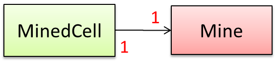
Option 1:
class MinedCell {
    private Mine mine;

    public MinedCell(Mine m) {
        if (m == null) {
            showError();
        }
        mine = m;
    }
    // ...
}
Option 1 forces us to keep a Mine without a MinedCell (until the MinedCell is created).
Option 2:
class MinedCell {
    private Mine mine;

    public MinedCell() {
        mine = new Mine();
    }
    // ...
}
Option 2 is more defensive because the Mine is immediately linked to a MinedCell.
A bidirectional association in the design (shown in (a)) is usually emulated at code level using two variables (as shown in (b)).
class Man {
    Woman girlfriend;

    void setGirlfriend(Woman w) {
        girlfriend = w;
    }
    // ...
}
class Woman {
    Man boyfriend;

    void setBoyfriend(Man m) {
        boyfriend = m;
    }
}
The two classes are meant to be used as follows:
Woman jean;
Man james;
// ...
james.setGirlfriend(jean);
jean.setBoyfriend(james);
Suppose the two classes were used like this instead:
Woman jean;
Man james, yong;
// ...
james.setGirlfriend(jean);
jean.setBoyfriend(yong);
Now James' girlfriend is Jean, while Jean's boyfriend is not James. This situation is a result of the code not being defensive enough to stop this "love triangle". In such a situation, you could say that the referential integrity has been violated. This means that there is an inconsistency in object references.

One way to prevent this situation is to implement the two classes as shown below. Note how the referential integrity is maintained.
public class Woman {
    private Man boyfriend;

    public void setBoyfriend(Man m) {
        if (boyfriend == m) {
            return;
        }
        if (boyfriend != null) {
            boyfriend.breakUp();
        }
        boyfriend = m;
        if (m != null) {
            m.setGirlfriend(this);
        }
    }

    public void breakUp() {
        boyfriend = null;
    }
    // ...
}
public class Man {
    private Woman girlfriend;

    public void setGirlfriend(Woman w) {
        if (girlfriend == w) {
            return;
        }
        if (girlfriend != null) {
            girlfriend.breakUp();
        }
        girlfriend = w;
        if (w != null) {
            w.setBoyfriend(this);
        }
    }
    public void breakUp() {
        girlfriend = null;
    }
    // ...
}
When james.setGirlfriend(jean) is executed, the code ensures that james breaks up with any current girlfriend before he accepts jean as his girlfriend. Furthermore, the code ensures that jean breaks up with any existing boyfriends before accepting james as her boyfriend.
It is not necessary to be 100% defensive all the time. While defensive code may be less prone to be misused or abused, such code can also be more complicated and slower to run.
The suitable degree of defensiveness depends on many factors such as:
- How critical is the system?
- Will the code be used by programmers other than the author?
- The level of programming language support for defensive programming
- The overhead of being defensive
Design-by-Contract Approach
is an approach for designing software that requires defining formal, precise and verifiable interface specifications for software components.
Suppose an operation is implemented with the behavior specified precisely in the API (preconditions, post conditions, exceptions etc.). When following the defensive approach, the code should first check if the preconditions have been met. Typically, exceptions are thrown if preconditions are violated. In contrast, the Design-by-Contract (DbC) approach to coding assumes that it is the responsibility of the caller to ensure all preconditions are met. The operation will honor the contract only if the preconditions have been met. If any of them have not been met, the behavior of the operation is "unspecified".
Languages such as Eiffel have native support for DbC. For example, preconditions of an operation can be specified in Eiffel and the language runtime will check precondition violations without the need to do it explicitly in the code. To follow the DbC approach in languages such as Java and C++ where there is no built-in DbC support, assertions can be used to confirm pre-conditions.
Integration
Introduction
Combining parts of a software product to form a whole is called integration. It is also one of the most troublesome tasks and it rarely goes smoothly.
Approaches
In terms of timing and frequency, there are two general approaches to integration: late and one-time, early and frequent.
Late and one-time: wait till all components are completed and integrate all finished components near the end of the project.
This approach is not recommended because integration often causes many component incompatibilities (due to previous miscommunications and misunderstandings) to surface which can lead to delivery delays i.e., Late integration → incompatibilities found → major rework required → cannot meet the delivery date.
Early and frequent: integrate early and evolve each part in parallel, in small steps, re-integrating frequently.
A can be written first. This can be done by one developer, possibly the one in charge of integration. After that, all developers can flesh out the skeleton in parallel, adding one feature at a time. After each feature is done, simply integrate the new code into the main system.
Big-bang integration: integrate all (or too many) components at the same time. More generally, integrating too many changes at the same time.
Big-bang is not recommended because it will uncover too many problems at the same time which could make debugging and bug-fixing more complex than when problems are uncovered incrementally.
Incremental integration: integrate a few components at a time. More generally, integrating changes gradually. This approach is better than big-bang integration because it surfaces integration problems in a more manageable way.
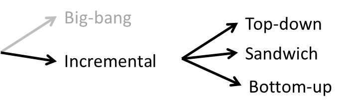
Based on the order in which components are integrated, incremental integration can be done in three ways.
Top-down integration: higher-level components are integrated before bringing in the lower-level components. One advantage of this approach is that higher-level problems can be discovered early. One disadvantage is that this requires the use of stubs in place of lower level components until the real lower-level components are integrated into the system. Otherwise, higher-level components cannot function as they depend on lower level ones.
Bottom-up integration: the reverse of top-down integration. Note that when integrating lower level components, may be needed to test the integrated components because the UI may not be integrated yet, just like how top-down integration needs stubs.
Sandwich integration: a mix of the top-down and bottom-up approaches. The idea is to do both top-down and bottom-up so as to 'meet' in the middle.
Build Automation
Build automation tools automate the steps of the build process, usually by means of build scripts.
In a non-trivial project, building a product from its source code can be a complex multistep process. For example, it can include steps such as: pull code from the revision control system, compile, link, run automated tests, automatically update release documents (e.g., build number), package into a distributable, push to repo, deploy to a server, delete temporary files created during building/testing, email developers of the new build, and so on. Furthermore, this build process can be done ‘on demand’, it can be scheduled (e.g., every day at midnight) or it can be triggered by various events (e.g., triggered by a code push to the revision control system).
Some of these build steps such as compiling, linking and packaging, are already automated in most modern IDEs. For example, several steps happen automatically when the ‘build’ button of the IDE is clicked. Some IDEs even allow customization of this build process to some extent.
However, most big projects use specialized build tools to automate complex build processes.
Some popular build tools relevant to Java developers: Gradle, Maven, Apache Ant, GNU Make
Some other build tools: Grunt (JavaScript), Rake (Ruby)
Some build tools also serve as dependency management tools. Modern software projects often depend on third party libraries that evolve constantly. That means developers need to download the correct version of the required libraries and update them regularly. Therefore, dependency management is an important part of build automation. Dependency management tools can automate that aspect of a project.
Maven and Gradle, in addition to managing the build process, can play the role of dependency management tools too.
An extreme application of build automation is called continuous integration (CI) in which integration, building, and testing happens automatically after each code change.
A natural extension of CI is Continuous Deployment (CD) where the changes are not only integrated continuously, but also deployed to end-users at the same time.
Some examples of CI/CD tools: Travis, Jenkins, Appveyor, CircleCI, GitHub Actions
Reuse
Introduction
Reuse is a major theme in software engineering practices. By reusing tried-and-tested components, the robustness of a new software system can be enhanced while reducing the manpower and time requirement. Reusable components come in many forms; it can be reusing a piece of code, a subsystem, or a whole software.
While you may be tempted to use many libraries/frameworks/platforms that seem to crop up on a regular basis and promise to bring great benefits, note that there are costs associated with reuse. Here are some:
- The reused code may be an overkill (think using a sledgehammer to crack a nut), increasing the size of, and/or degrading the performance of, your software.
- The reused software may not be mature/stable enough to be used in an important product. That means the software can change drastically and rapidly, possibly in ways that break your software.
- Non-mature software has the risk of dying off as fast as they emerged, leaving you with a dependency that is no longer maintained.
- The license of the reused software (or its dependencies) restrict how you can use/develop your software.
- The reused software might have bugs, missing features, or security vulnerabilities that are important to your product, but not so important to the maintainers of that software, which means those flaws will not get fixed as fast as you need them to.
- Malicious code can sneak into your product via compromised dependencies.
APIs
An Application Programming Interface (API) specifies the interface through which other programs can interact with a software component. It is a contract between the component and its clients.
A class has an API (e.g., API of the Java String class, API of the Python str class) which is a collection of public methods that you can invoke to make use of the class.
The GitHub API is a collection of web request formats that the GitHub server accepts and their corresponding responses. You can write a program that interacts with GitHub through that API.
When developing large systems, if you define the API of each component early, the development team can develop the components in parallel because the future behavior of the other components are now more predictable.
An API should be well-designed (i.e., should cater for the needs of its users) and well-documented.
When you write software consisting of multiple components, you need to define the API of each component.
One approach is to let the API emerge and evolve over time as you write code.
Another approach is to define the API up-front. Doing so allows us to develop the components in parallel.
You can use UML sequence diagrams to analyze the required interactions between components in order to discover the required API. Given below is an example.
Example:
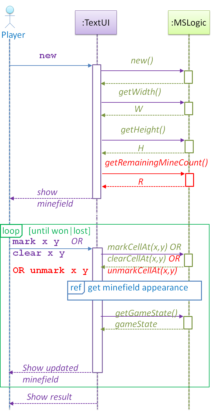
As you analyze the interactions between components using sequence diagrams, you discover the API of those components. For example, the diagram above tells us that the MSLogic component API should have the methods:
new()getWidth:intgetHeight():intgetRemainingMineCount():int
More details can be included to increase the precision of the method definitions before coding. Such precision is important to avoid misunderstandings between the developer of the class and developers of other classes that interact with the class.
- Operation: newGame(): void
- Description: Generates a new WxH minefield with M mines. Any existing minefield will be overwritten.
- Preconditions: None
- Postconditions: A new minefield is created. Game state is READY.
Preconditions are the conditions that must be true before calling this operation. Postconditions describe the system after the operation is complete. Note that postconditions do not say what happens during the operation. Here is another example:
- Operation: clearCellAt(int x, int y): void
- Description: Records the cell at x, y as cleared.
- Parameters: x, y coordinates of the cell
- Preconditions: game state is READY or IN_PLAY. x and y are in 0..(H-1) and 0..(W-1), respectively.
- Postconditions: Cell at x, y changes state to ZERO, ONE, TWO, THREE, …, EIGHT, or INCORRECTLY_CLEARED. Game state changes to IN_PLAY, WON or LOST as appropriate.
Libraries
A library is a collection of modular code that is general and can be used by other programs.
Java classes you get with the JDK (such as String, ArrayList, HashMap, etc.) are library classes that are provided in the default Java distribution.
Natty is a Java library that can be used for parsing strings that represent dates e.g., The 31st of April in the year 2008
built-in modules you get with Python (such as csv, random, sys, etc.) are libraries that are provided in the default Python distribution. Classes such as list, str, dict are built-in library classes that you get with Python.
Colorama is a Python library that can be used for colorizing text in a CLI.
These are the typical steps required to use a library:
- Read the documentation to confirm that its functionality fits your needs.
- Check the license to confirm that it allows reuse in the way you plan to reuse it. For example, some libraries might allow non-commercial use only.
- Download the library and make it accessible to your project. Alternatively, you can configure your to do it for you.
- Call the library API from your code where you need to use the library's functionality.
Frameworks
The overall structure and execution flow of a specific category of software systems can be very similar. The similarity is an opportunity to reuse at a high scale.
Running example:
IDEs for different programming languages are similar in how they support editing code, organizing project files, debugging, etc.
A software framework is a reusable implementation of a software (or part thereof) providing generic functionality that can be selectively customized to produce a specific application.
Running example:
Eclipse is an IDE framework that can be used to create IDEs for different programming languages.
Some frameworks provide a complete implementation of a default behavior which makes them immediately usable.
Running example:
Eclipse is a fully functional Java IDE out-of-the-box.
A framework facilitates the adaptation and customization of some desired functionality.
Running example:
The Eclipse plugin system can be used to create an IDE for different programming languages while reusing most of the existing IDE features of Eclipse.
e.g., https://marketplace.eclipse.org/content/pydev-python-ide-eclipse
Some frameworks cover only a specific component or an aspect.
JavaFX is a framework for creating Java GUIs. Tkinter is a GUI framework for Python.
More examples of frameworks
- Frameworks for web-based applications: Drupal (PHP), Django (Python), Ruby on Rails (Ruby), Spring (Java)
- Frameworks for testing: JUnit (Java), unittest (Python), Jest (JavaScript)
Although both frameworks and libraries are reuse mechanisms, there are notable differences:
Libraries are meant to be used ‘as is’ while frameworks are meant to be customized/extended. e.g., writing plugins for Eclipse so that it can be used as an IDE for different languages (C++, PHP, etc.), adding modules and themes to Drupal, and adding test cases to JUnit.
Your code calls the library code while the framework code calls your code. Frameworks use a technique called inversion of control, aka the “Hollywood principle” (i.e., don’t call us, we’ll call you!). That is, you write code that will be called by the framework, e.g., writing test methods that will be called by the JUnit framework. In the case of libraries, your code calls libraries.
Platforms
A platform provides a runtime environment for applications. A platform is often bundled with various libraries, tools, frameworks, and technologies in addition to a runtime environment but the defining characteristic of a software platform is the presence of a runtime environment.
Technically, an operating system can be called a platform. For example, Windows PC is a platform for desktop applications while iOS is a platform for mobile applications.
Two well-known examples of platforms are JavaEE and .NET, both of which sit above the operating systems layer, and are used to develop enterprise applications. Infrastructure services such as connection pooling, load balancing, remote code execution, transaction management, authentication, security, messaging etc. are done similarly in most enterprise applications. Both JavaEE and .NET provide these services to applications in a customizable way without developers having to implement them from scratch every time.
- JavaEE (Java Enterprise Edition) is both a framework and a platform for writing enterprise applications. The runtime used by JavaEE applications is the JVM (Java Virtual Machine) that can run on different Operating Systems.
- .NET is a similar platform and framework. Its runtime is called CLR (Common Language Runtime) and it is usually used on Windows machines.
Cloud Computing
Cloud computing is the delivery of computing as a service over the network, rather than a product running on a local machine. This means the actual hardware and software is located at a remote location, typically, at a large server farm, while users access them over the network. Maintenance of the hardware and software is managed by the cloud provider while users typically pay for only the amount of services they use. This model is similar to the consumption of electricity; the power company manages the power plant, while the consumers pay them only for the electricity used. The cloud computing model optimizes hardware and software utilization and reduces the cost to consumers. Furthermore, users can scale up/down their utilization at will without having to upgrade their hardware and software. The traditional non-cloud model of computing is similar to everyone buying their own generators to create electricity for their own use.

source: https://commons.wikimedia.org
Cloud computing can deliver computing services at three levels:
Infrastructure as a service (IaaS) delivers computer infrastructure as a service. For example, a user can deploy virtual servers on the cloud instead of buying physical hardware and installing server software on them. Another example would be a customer using storage space on the cloud for off-site storage of data. Rackspace is an example of an IaaS cloud provider. Amazon Elastic Compute Cloud (Amazon EC2) is another one.
Platform as a service (PaaS) provides a platform on which developers can build applications. Developers do not have to worry about infrastructure issues such as deploying servers or load balancing as is required when using IaaS. Those aspects are automatically taken care of by the platform. The price to pay is reduced flexibility; applications written on PaaS are limited to facilities provided by the platform. A PaaS example is the Google App Engine where developers can build applications using Java, Python, PHP, or Go whereas Amazon EC2 allows users to deploy applications written in any language on their virtual servers.
Software as a service (SaaS) allows applications to be accessed over the network instead of installing them on a local machine. For example, Google Docs is a SaaS word processing software, while Microsoft Word is a traditional word processing software.
SECTION: QUALITY ASSURANCE
Quality Assurance
Introduction
Software Quality Assurance (QA) is the process of ensuring that the software being built has the required levels of quality.
While testing is the most common activity used in QA, there are other complementary techniques such as static analysis, code reviews, and formal verification.
Quality Assurance = Validation + Verification
QA involves checking two aspects:
- Validation: are you building the right system i.e., are the requirements correct?
- Verification: are you building the system right i.e., are the requirements implemented correctly?
Whether something belongs under validation or verification is not that important. What is more important is that both are done, instead of limiting to only verification (i.e., remember that the requirements can be wrong too).
Code Reviews
Code review is the systematic examination of code with the intention of finding where the code can be improved.
Reviews can be done in various forms. Some examples below:
Pull Request reviews
- Project Management Platforms such as GitHub and BitBucket allow the new code to be proposed as Pull Requests and provide the ability for others to review the code in the PR.
In pair programming
- As pair programming involves two programmers working on the same code at the same time, there is an implicit review of the code by the other member of the pair.
Formal inspections
Inspections involve a group of people systematically examining project artifacts to discover defects. Members of the inspection team play various roles during the process, such as:
- the author - the creator of the artifact
- the moderator - the planner and executor of the inspection meeting
- the secretary - the recorder of the findings of the inspection
- the inspector/reviewer - the one who inspects/reviews the artifact
Advantages of code review over testing:
- It can detect functionality defects as well as other problems such as coding standard violations.
- It can verify non-code artifacts and incomplete code.
- It does not require test drivers or stubs.
Disadvantages:
- It is a manual process and therefore, error prone.
Static Analysis
Static analysis: Static analysis is the analysis of code without actually executing the code.
Static analysis of code can find useful information such as unused variables, unhandled exceptions, style errors, and statistics. Most modern IDEs come with some inbuilt static analysis capabilities. For example, an IDE can highlight unused variables as you type the code into the editor.
The term static in static analysis refers to the fact that the code is analyzed without executing the code. In contrast, dynamic analysis requires the code to be executed to gather additional information about the code e.g., performance characteristics.
Higher-end static analysis tools (static analyzers) can perform more complex analysis such as locating potential bugs, memory leaks, inefficient code structures, etc.
Some example static analyzers for Java: CheckStyle, PMD, FindBugs
Linters are a subset of static analyzers that specifically aim to locate areas where the code can be made 'cleaner'.
Formal Verification
Formal verification uses mathematical techniques to prove the correctness of a program.
Advantages:
- Formal verification can be used to prove the absence of errors. In contrast, testing can only prove the presence of errors, not their absence.
Disadvantages:
- It only proves the compliance with the specification, but not the actual utility of the software.
- It requires highly specialized notations and knowledge which makes it an expensive technique to administer. Therefore, formal verifications are more commonly used in safety-critical software such as flight control systems.
Testing
Introduction
Testing: Operating a system or component under specified conditions, observing or recording the results, and making an evaluation of some aspect of the system or component. –- source: IEEE
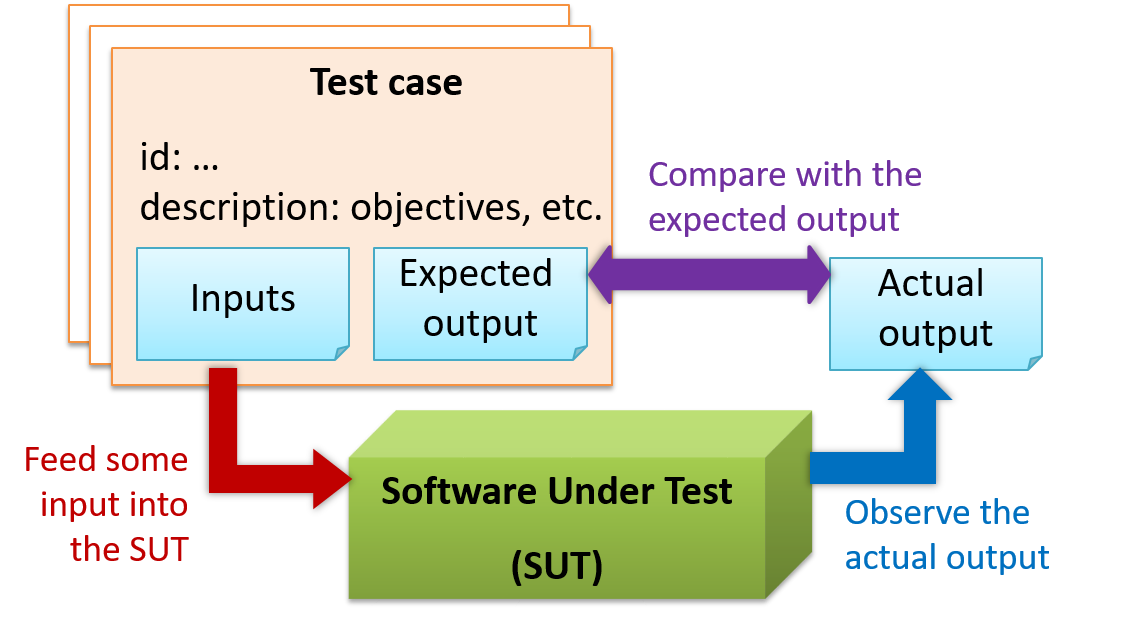
When testing, you execute a set of test cases. A test case specifies how to perform a test. At a minimum, it specifies the input to the software under test (SUT) and the expected behavior.
Example: A minimal test case for testing a browser:
- Input – Start the browser using a blank page (vertical scrollbar disabled). Then, load
longfile.htmllocated in thetest datafolder. - Expected behavior – The scrollbar should be automatically enabled upon loading
longfile.html.
Test cases can be determined based on the specification, reviewing similar existing systems, or comparing to the past behavior of the SUT.
For each test case you should do the following:
- Feed the input to the SUT
- Observe the actual output
- Compare actual output with the expected output
A test case failure is a mismatch between the expected behavior and the actual behavior. A failure indicates a potential defect (or a bug) -- we say 'potential' because the error could be in the test case itself.
Example: In the browser example above, a test case failure is implied if the scrollbar remains disabled after loading longfile.html. The defect/bug causing that failure could be an uninitialized variable.
Testability is an indication of how easy it is to test an SUT. As testability depends a lot on the design and implementation, you should try to increase the testability when you design and implement software. The higher the testability, the easier it is to achieve better quality software.
Testing Types
Unit Testing
Unit testing: testing individual units (methods, classes, subsystems, ...) to ensure each piece works correctly.
In OOP code, it is common to write one or more unit tests for each public method of a class.
Here are the code skeletons for a Foo class containing two methods and a FooTest class that contains unit tests for those two methods.
class Foo {
    String read() {
        // ...
    }

    void write(String input) {
        // ...
    }

}
class FooTest {

    @Test
    void read() {
        // a unit test for Foo#read() method
    }

    @Test
    void write_emptyInput_exceptionThrown() {
        // a unit tests for Foo#write(String) method
    }

    @Test
    void write_normalInput_writtenCorrectly() {
        // another unit tests for Foo#write(String) method
    }
}
import unittest

class Foo:
  def read(self):
      # ...

  def write(self, input):
      # ...


class FooTest(unittest.TestCase):

  def test_read(self):
      # a unit test for read() method

  def test_write_emptyIntput_ignored(self):
      # a unit test for write(string) method

  def test_write_normalInput_writtenCorrectly(self):
      # another unit test for write(string) method
A proper unit test requires the unit to be tested in isolation so that bugs in the cannot influence the test i.e., bugs outside of the unit should not affect the unit tests.
If a Logic class depends on a Storage class, unit testing the Logic class requires isolating the Logic class from the Storage class.
Stubs can isolate the from its dependencies.
Stub: A stub has the same interface as the component it replaces, but its implementation is so simple that it is unlikely to have any bugs. It mimics the responses of the component, but only for a limited set of predetermined inputs. That is, it does not know how to respond to any other inputs. Typically, these mimicked responses are hard-coded in the stub rather than computed or retrieved from elsewhere, e.g., from a database.
Consider the code below:
class Logic {
    Storage s;

    Logic(Storage s) {
        this.s = s;
    }

    String getName(int index) {
        return "Name: " + s.getName(index);
    }
}
interface Storage {
    String getName(int index);
}
class DatabaseStorage implements Storage {

    @Override
    public String getName(int index) {
        return readValueFromDatabase(index);
    }

    private String readValueFromDatabase(int index) {
        // retrieve name from the database
    }
}
Normally, you would use the Logic class as follows (note how the Logic object depends on a DatabaseStorage object to perform the getName() operation):
Logic logic = new Logic(new DatabaseStorage());
String name = logic.getName(23);
You can test it like this:
@Test
void getName() {
    Logic logic = new Logic(new DatabaseStorage());
    assertEquals("Name: John", logic.getName(5));
}
However, this logic object being tested is making use of a DataBaseStorage object which means a bug in the DatabaseStorage class can affect the test. Therefore, this test is not testing Logic in isolation from its dependencies and hence it is not a pure unit test.
Here is a stub class you can use in place of DatabaseStorage:
class StorageStub implements Storage {

    @Override
    public String getName(int index) {
        if (index == 5) {
            return "Adam";
        } else {
            throw new UnsupportedOperationException();
        }
    }
}
Note how the StorageStub has the same interface as DatabaseStorage, but is so simple that it is unlikely to contain bugs, and is pre-configured to respond with a hard-coded response, presumably, the correct response DatabaseStorage is expected to return for the given test input.
Here is how you can use the stub to write a unit test. This test is not affected by any bugs in the DatabaseStorage class and hence is a pure unit test.
@Test
void getName() {
    Logic logic = new Logic(new StorageStub());
    assertEquals("Name: Adam", logic.getName(5));
}
In addition to Stubs, there are other type of replacements you can use during testing, e.g., Mocks, Fakes, Dummies, Spies.
Integration Testing
Integration testing : testing whether different parts of the software work together (i.e., integrates) as expected. Integration tests aim to discover bugs in the 'glue code' related to how components interact with each other. These bugs are often the result of misunderstanding what the parts are supposed to do vs what the parts are actually doing.
Suppose a class Car uses classes Engine and Wheel. If the Car class assumed a Wheel can support a speed of up to 200 mph but the actual Wheel can only support a speed of up to 150 mph, it is the integration test that is supposed to uncover this discrepancy.
System Testing
System testing: take the whole system and test it against the system specification.
System testing is typically done by a testing team (also called a QA team).
System test cases are based on the specified external behavior of the system. Sometimes, system tests go beyond the bounds defined in the specification. This is useful when testing that the system fails 'gracefully' when pushed beyond its limits.
Suppose the SUT is a browser that is supposedly capable of handling web pages containing up to 5000 characters. Given below is a test case to test if the SUT fails gracefully if pushed beyond its limits.
Test case: load a web page that is too big
* Input: loads a web page containing more than 5000 characters.
* Expected behavior: aborts the loading of the page
  and shows a meaningful error message.
This test case would fail if the browser attempted to load the large file anyway and crashed.
System testing includes testing against non-functional requirements too. Here are some examples:
- Performance testing – to ensure the system responds quickly.
- Load testing (also called stress testing or scalability testing) – to ensure the system can work under heavy load.
- Security testing – to test how secure the system is.
- Compatibility testing, interoperability testing – to check whether the system can work with other systems.
- Usability testing – to test how easy it is to use the system.
- Portability testing – to test whether the system works on different platforms.
Alpha-Beta Testing
Alpha testing is performed by the users, under controlled conditions set by the software development team.
Beta testing is performed by a selected subset of target users of the system in their natural work setting.
An open beta release is the release of not-yet-production-quality-but-almost-there software to the general population. For example, Google’s Gmail was in 'beta' for many years before the label was finally removed.
Dogfooding
Dogfooding is when creators use their own product in order to experience how end users experience the product. The term is supposedly derived from the phrase "eating our own dogfood". Dogfooding is different from regular testing in that you become an end user, rather than pretend to be an end user.
For example, suppose a company produces an email client software. Then, getting some of the employees to use that software for their day-to-day emailing would be dogfooding. Such longer-term, consistent, and authentic use of the software can point to areas of improvement that regular testing (which is often short-term and 'simulated') might not encounter.
Note that dogfooding to be useful, observations need to be deliberately collected and processed i.e., just using the product itself is not enough.
Developer Testing
Developer testing is the testing done by the developers themselves as opposed to dedicated testers or end-users.
Delaying testing until the full product is complete has a number of disadvantages:
- Locating the cause of a test case failure is difficult due to the larger search space; in a large system, the search space could be millions of lines of code, written by hundreds of developers! The failure may also be due to multiple inter-related bugs.
- Fixing a bug found during such testing could result in major rework, especially if the bug originated from the design or during requirements specification i.e., a faulty design or faulty requirements.
- One bug might 'hide' other bugs, which could emerge only after the first bug is fixed.
- The delivery may have to be delayed if too many bugs are found during testing.
Therefore, it is better to do early testing, as hinted by the popular rule of thumb given below, also illustrated by the graph below it.
The earlier a bug is found, the easier and cheaper to have it fixed.
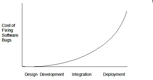
Such early testing software is usually, and often by necessity, done by the developers themselves i.e., developer testing.
Exploratory vs Scripted Testing
Here are two alternative approaches to testing a software: Scripted testing and Exploratory testing.
Scripted testing: First write a set of test cases based on the expected behavior of the SUT, and then perform testing based on that set of test cases.
Exploratory testing: Devise test cases on-the-fly, creating new test cases based on the results of the past test cases.
Exploratory testing is ‘the simultaneous learning, test design, and test execution’ [source: bach-et-explained] whereby the nature of the follow-up test case is decided based on the behavior of the previous test cases. In other words, running the system and trying out various operations. It is called exploratory testing because testing is driven by observations during testing. Exploratory testing usually starts with areas identified as error-prone, based on the tester’s past experience with similar systems. One tends to conduct more tests for those operations where more faults are found.
Here is an example thought process behind a segment of an exploratory testing session:
“Hmm... looks like feature x is broken. This usually means feature n and k could be broken too; you need to look at them soon. But before that, you should give a good test run to feature y because users can still use the product if feature y works, even if x doesn’t work. Now, if feature y doesn’t work 100%, you have a major problem and this has to be made known to the development team sooner rather than later...”
Exploratory testing is also known as reactive testing, error guessing technique, attack-based testing, and bug hunting.
Which approach is better – scripted or exploratory? A mix is better.
The success of exploratory testing depends on the tester’s prior experience and intuition. Exploratory testing should be done by experienced testers, using a clear strategy/plan/framework. Ad-hoc exploratory testing by unskilled or inexperienced testers without a clear strategy is not recommended for real-world non-trivial systems. While exploratory testing may allow us to detect some problems in a relatively short time, it is not prudent to use exploratory testing as the sole means of testing a critical system.
Scripted testing is more systematic, and hence, likely to discover more bugs given sufficient time, while exploratory testing would aid in quick error discovery, especially if the tester has a lot of experience in testing similar systems.
In some contexts, you will achieve your testing mission better through a more scripted approach; in other contexts, your mission will benefit more from the ability to create and improve tests as you execute them. I find that most situations benefit from a mix of scripted and exploratory approaches. --[source: bach-et-explained]
Acceptance Testing
Acceptance testing (aka User Acceptance Testing (UAT): test the system to ensure it meets the user requirements.
Acceptance tests give an assurance to the customer that the system does what it is intended to do. Acceptance test cases are often defined at the beginning of the project, usually based on the use case specification. Successful completion of UAT is often a prerequisite to the project sign-off.
Acceptance testing comes after system testing. Similar to system testing, acceptance testing involves testing the whole system.
Some differences between system testing and acceptance testing:
| System Testing | Acceptance Testing |
|---|---|
| Done against the system specification | Done against the requirements specification |
| Done by testers of the project team | Done by a team that represents the customer |
| Done on the development environment or a test bed | Done on the deployment site or on a close simulation of the deployment site |
| Both negative and positive test cases | More focus on positive test cases |
Note: negative test cases: cases where the SUT is not expected to work normally e.g., incorrect inputs; positive test cases: cases where the SUT is expected to work normally
Requirement specification versus system specification
The requirement specification need not be the same as the system specification. Some example differences:
| Requirements specification | System specification |
|---|---|
| limited to how the system behaves in normal working conditions | can also include details on how it will fail gracefully when pushed beyond limits, how to recover, etc. specification |
| written in terms of problems that need to be solved (e.g., provide a method to locate an email quickly) | written in terms of how the system solves those problems (e.g., explain the email search feature) |
| specifies the interface available for intended end-users | could contain additional APIs not available for end-users (for the use of developers/testers) |
However, in many cases one document serves as both a requirement specification and a system specification.
Passing system tests does not necessarily mean passing acceptance testing. Some examples:
- The system might work on the testbed environments but might not work the same way in the deployment environment, due to subtle differences between the two environments.
- The system might conform to the system specification but could fail to solve the problem it was supposed to solve for the user, due to flaws in the system design.
Regression Testing
When you modify a system, the modification may result in some unintended and undesirable effects on the system. Such an effect is called a regression.
Regression testing is the re-testing of the software to detect regressions. The typical way to detect regressions is retesting all related components, even if they had been tested before.
Regression testing is more effective when it is done frequently, after each small change. However, doing so can be prohibitively expensive if testing is done manually. Hence, regression testing is more practical when it is automated.
Test Automation
An automated test case can be run programmatically and the result of the test case (pass or fail) is determined programmatically. Compared to manual testing, automated testing reduces the effort required to run tests repeatedly and increases precision of testing (because manual testing is susceptible to human errors).
A simple way to semi-automate testing of a CLI (Command Line Interface) app is by using input/output re-direction. Here are the high-level steps:
- First, you feed the app with a sequence of test inputs that is stored in a file while redirecting the output to another file.
- Next, you compare the actual output file with another file containing the expected output.
Let's assume you are testing a CLI app called AddressBook. Here are the detailed steps:
Store the test input in the text file
input.txt.Store the output you expect from the SUT in another text file
expected.txt.Run the program as given below, which will redirect the text in
input.txtas the input toAddressBookand similarly, will redirect the output ofAddressBookto a text fileoutput.txt. Note that this does not require any changes inAddressBookcode.java AddressBook < input.txt > output.txtThe way to run a CLI program differs based on the language.
e.g., In Python, assuming the code is inAddressBook.pyfile, use the command
python AddressBook.py < input.txt > output.txtIf you are using Windows, use a normal MS-DOS terminal (i.e.,
cmd.exe) to run the app, not a PowerShell window.
Next, you compare
output.txtwith theexpected.txt. This can be done using a utility such as Windows'FC(i.e., File Compare) command, Unix'sdiffcommand, or a GUI tool such as WinMerge.FC output.txt expected.txt
Note that the above technique is only suitable when testing CLI apps, and only if the exact output can be predetermined. If the output varies from one run to the other (e.g., it contains a time stamp), this technique will not work. In those cases, you need more sophisticated ways of automating tests.
A test driver is the code that ‘drives’ the for the purpose of testing i.e., invoking the SUT with test inputs and verifying if the behavior is as expected.
PayrollTest ‘drives’ the Payroll class by sending it test inputs and verifies if the output is as expected.
public class PayrollTest {
    public static void main(String[] args) throws Exception {

        // test setup
        Payroll p = new Payroll();

        // test case 1
        p.setEmployees(new String[]{"E001", "E002"});
        // automatically verify the response
        if (p.totalSalary() != 6400) {
            throw new Error("case 1 failed ");
        }

        // test case 2
        p.setEmployees(new String[]{"E001"});
        if (p.totalSalary() != 2300) {
            throw new Error("case 2 failed ");
        }

        // more tests...

        System.out.println("All tests passed");
    }
}
JUnit is a tool for automated testing of Java programs. Similar tools are available for other languages and for automating different types of testing.
This is an automated test for a Payroll class, written using JUnit libraries.
    // other test methods

    @Test
    public void testTotalSalary() {
        Payroll p = new Payroll();

        // test case 1
        p.setEmployees(new String[]{"E001", "E002"});
        assertEquals(6400, p.totalSalary());

        // test case 2
        p.setEmployees(new String[]{"E001"});
        assertEquals(2300, p.totalSalary());

        // more tests...
    }
Most modern IDEs have integrated support for testing tools. The figure below shows the JUnit output when running some JUnit tests using the Eclipse IDE.
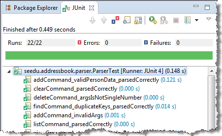
If a software product has a GUI (Graphical User Interface) component, all product-level testing (i.e., the types of testing mentioned above) need to be done using the GUI. However, testing the GUI is much harder than testing the CLI (Command Line Interface) or API, for the following reasons:
- Most GUIs can support a large number of different operations, many of which can be performed in any arbitrary order.
- GUI operations are more difficult to automate than API testing. Reliably automating GUI operations and automatically verifying whether the GUI behaves as expected is harder than calling an operation and comparing its return value with an expected value. Therefore, automated regression testing of GUIs is rather difficult.
- The appearance of a GUI (and sometimes even behavior) can be different across platforms and even environments. For example, a GUI can behave differently based on whether it is minimized or maximized, in focus or out of focus, and in a high resolution display or a low resolution display.
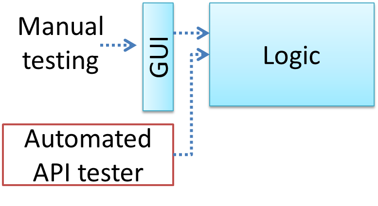
Moving as much logic as possible out of the GUI can make GUI testing easier. That way, you can bypass the GUI to test the rest of the system using automated API testing. While this still requires the GUI to be tested, the number of such test cases can be reduced as most of the system will have been tested using automated API testing.
There are testing tools that can automate GUI testing.
Some tools used for automated GUI testing:
TestFX can do automated testing of JavaFX GUIs
Visual Studio supports the ‘record replay’ type of GUI test automation.
Selenium can be used to automate testing of web application UIs
Test Coverage
Test coverage is a metric used to measure the extent to which testing exercises the code i.e., how much of the code is 'covered' by the tests.
Here are some examples of different coverage criteria:
- Function/method coverage : based on functions executed e.g., testing executed 90 out of 100 functions.
- Statement coverage : based on the number of lines of code executed e.g., testing executed 23k out of 25k LOC.
- Decision/branch coverage : based on the decision points exercised e.g., an
ifstatement evaluated to bothtrueandfalsewith separate test cases during testing is considered 'covered'. - Condition coverage : based on the boolean sub-expressions, each evaluated to both true and false with different test cases. Condition coverage is not the same as the decision coverage.
if(x > 2 && x < 44) is considered one decision point but two conditions.
For 100% branch or decision coverage, two test cases are required:
(x > 2 && x < 44) == true: [e.g.,x == 4](x > 2 && x < 44) == false: [e.g.,x == 100]
For 100% condition coverage, three test cases are required:
(x > 2) == true,(x < 44) == true: [e.g.,x == 4] [see note 1](x < 44) == false: [e.g.,x == 100](x > 2) == false: [e.g.,x == 0]
Note 1: A case where both conditions are true is needed because most execution environments use a short circuiting behavior for compound boolean expressions e.g., given an expression c1 && c2, c2 will not be evaluated if c1 is false (as the final result is going to be false anyway).
- Path coverage measures coverage in terms of possible paths through a given part of the code executed. 100% path coverage means all possible paths have been executed. A commonly used notation for path analysis is called the Control Flow Graph (CFG).
Consider the following Java method.
void findRate(int input) {
    if (input == 0) {
        return 0;
    }
    cap = 100/input;
    if (cap < 0) {
        return -1;
    } else {
        return cap;
    }
}
It has 3 paths, as follows:
- enter ->
2->3-> exit (can be triggered by input0) - enter ->
2->5->6->7-> exit (can be triggered by input-5) - enter ->
2->5->6->9-> exit (can be triggered by input8)
So, to achieve 100% path coverage, we need at least 3 test cases (e.g., 0, -5, 8).
A loop can increase the path count greatly.
void sayHello(List<String> names) {
    for (String n : names) {
        System.out.println(n);
    }
}
The number of paths through this method is very large, as each possible length of names produces a unique path.
- enter ->
2-> exit (ifnamesis empty) - enter ->
2->3-> exit (ifnameshas one entry) - enter ->
2->3->2->3-> exit (ifnameshas two entries) 1 ...
So, achieving 100% path coverage of this method will be extremely difficult.
- Entry/exit coverage measures coverage in terms of possible calls to and exits from the operations in the SUT.
Entry points refer to all places from which the method is called from the rest of the code i.e., all places where the control is handed over to the method in concern.
Exit points refer to points at which the control is returned to the caller e.g., return statements, throwing of exceptions.
Measuring coverage is often done using coverage analysis tools. Most IDEs have inbuilt support for measuring test coverage, or at least have plugins that can measure test coverage.
Coverage analysis can be useful in improving the quality of testing e.g., if a set of test cases does not achieve 100% branch coverage, more test cases can be added to cover missed branches.
Measuring code coverage in IntelliJ IDEA (watch from 4 minutes 50 seconds mark)
Dependency Injection
Dependency injection is the process of 'injecting' objects to replace current dependencies with a different object. This is often used to inject stubs to isolate the from its so that it can be tested in isolation.
A Foo object normally depends on a Bar object, but you can inject a BarStub object so that the Foo object no longer depends on a Bar object. Now you can test the Foo object in isolation from the Bar object.
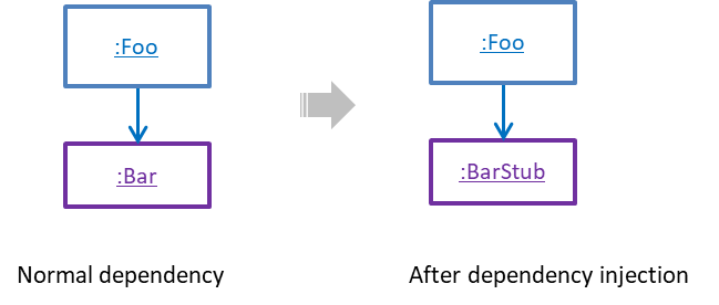
Polymorphism can be used to implement dependency injection, as can be seen in the example given in [Quality Assurance → Testing → Unit Testing → Stubs] where a stub is injected to replace a dependency.
Here is another example of using polymorphism to implement dependency injection:
Suppose you want to unit test Payroll#totalSalary() given below. The method depends on the SalaryManager object to calculate the return value. Note how the setSalaryManager(SalaryManager) can be used to inject a SalaryManager object to replace the current SalaryManager object.
class Payroll {
    private SalaryManager manager = new SalaryManager();
    private String[] employees;

    void setEmployees(String[] employees) {
        this.employees = employees;
    }

    void setSalaryManager(SalaryManager sm) {
        this.manager = sm;
    }

    double totalSalary() {
        double total = 0;
        for (int i = 0; i < employees.length; i++) {
            total += manager.getSalaryForEmployee(employees[i]);
        }
        return total;
    }
}


class SalaryManager {
    double getSalaryForEmployee(String empID) {
        // code to access employee’s salary history
        // code to calculate total salary paid and return it
    }
}
During testing, you can inject a SalaryManagerStub object to replace the SalaryManager object.
class PayrollTest {
    public static void main(String[] args) {
        // test setup
        Payroll p = new Payroll();
        // dependency injection
        p.setSalaryManager(new SalaryManagerStub());
        // test case 1
        p.setEmployees(new String[]{"E001", "E002"});
        assertEquals(2500.0, p.totalSalary());
        // test case 2
        p.setEmployees(new String[]{"E001"});
        assertEquals(1000.0, p.totalSalary());
        // more tests ...
    }
}


class SalaryManagerStub extends SalaryManager {
    /** Returns hard coded values used for testing */
    double getSalaryForEmployee(String empID) {
        if (empID.equals("E001")) {
            return 1000.0;
        } else if (empID.equals("E002")) {
            return 1500.0;
        } else {
            throw new Error("unknown id");
        }
    }
}
TDD
Test-Driven Development(TDD) advocates writing the tests before writing the SUT, while evolving functionality and tests in small increments. In TDD you first define the precise behavior of the SUT using test code, and then update the SUT to match the specified behavior. While TDD has its fair share of detractors, there are many who consider it a good way to reduce defects. One big advantage of TDD is that it guarantees the code is testable.
Note that TDD does not imply writing all the test cases first before writing functional code. Rather, proceed in small steps:
- Decide what behavior to implement.
- Write/modify a test case to test that behavior.
- Run the test cases and watch them fail.
- Implement the behavior.
- Run the test cases.
- Keep modifying the code and rerunning test cases until they all pass.
- Refactor code to improve quality.
- Repeat the cycle for each small unit of behavior that needs to be implemented.
Some TDD proponents cite the following as the three rules of TDD, that once again emphasize the need to proceed in very small steps:
- You are not allowed to write any production code unless it is to make a failing unit test pass.
- You are not allowed to write any more of a unit test than is sufficient to fail; and compilation failures are failures.
- You are not allowed to write any more production code than is sufficient to pass the one failing unit test.
Test Case Design
Introduction
Except for trivial , is not practical because such testing often requires a massive/infinite number of test cases.
Consider the test cases for adding a string object to a :
- Add an item to an empty collection.
- Add an item when there is one item in the collection.
- Add an item when there are 2, 3, .... n items in the collection.
- Add an item that has an English, a French, a Spanish, ... word.
- Add an item that is the same as an existing item.
- Add an item immediately after adding another item.
- Add an item immediately after system startup.
- ...
Exhaustive testing of this operation can take many more test cases.
Program testing can be used to show the presence of bugs, but never to show their absence! --Edsger Dijkstra
Every test case adds to the cost of testing. In some systems, a single test case can cost thousands of dollars e.g. on-field testing of flight-control software. Therefore, test cases need to be designed to make the best use of testing resources. In particular:
Testing should be effective i.e., it finds a high percentage of existing bugs e.g., a set of test cases that finds 60 defects is more effective than a set that finds only 30 defects in the same system.
Testing should be efficient i.e., it has a high rate of success (bugs found/test cases) a set of 20 test cases that finds 8 defects is more efficient than another set of 40 test cases that finds the same 8 defects.
For testing to be , each new test you add should be targeting a potential fault that is not already targeted by existing test cases. There are test case design techniques that can help us improve the E&E of testing.
A positive test case is when the test is designed to produce an expected/valid behavior. On the other hand, a negative test case is designed to produce a behavior that indicates an invalid/unexpected situation, such as an error message.
Consider the testing of the method print(Integer i) which prints the value of i.
- A positive test case:
i == new Integer(50); - A negative test case:
i == null;
Test case design can be of three types, based on how much of the SUT's internal details are considered when designing test cases:
Black-box (aka specification-based or responsibility-based) approach: test cases are designed exclusively based on the SUT’s specified external behavior.
White-box (aka glass-box or structured or implementation-based) approach: test cases are designed based on what is known about the SUT’s implementation, i.e., the code.
Gray-box approach: test case design uses some important information about the implementation. For example, if the implementation of a sort operation uses different algorithms to sort lists shorter than 1000 items and lists longer than 1000 items, more meaningful test cases can then be added to verify the correctness of both algorithms.
Equivalence Partitions
Consider the testing of the following operation.
isValidMonth(m) : returns true if m (an int) is in the range [1..12]
It is inefficient and impractical to test this method for all integer values [-MIN_INT to MAX_INT]. Fortunately, there is no need to test all possible input values. For example, if the input value 233 fails to produce the correct result, the input 234 is likely to fail too; there is no need to test both.
In general, most SUTs do not treat each input in a unique way. Instead, they process all possible inputs in a small number of distinct ways. That means a range of inputs is treated the same way inside the SUT. Equivalence partitioning (EP) is a test case design technique that uses the above observation to improve the E&E of testing.
Equivalence partition (aka equivalence class): A group of test inputs that are likely to be processed by the SUT in the same way.
By dividing possible inputs into equivalence partitions you can,
- avoid testing too many inputs from one partition. Testing too many inputs from the same partition is unlikely to find new bugs. This increases the efficiency of testing by reducing redundant test cases.
- ensure all partitions are tested. Missing partitions can result in bugs going unnoticed. This increases the effectiveness of testing by increasing the chance of finding bugs.
Equivalence partitions (EPs) are usually derived from the specifications of the SUT.
These could be EPs for the isValidMonth example:
- [MIN_INT ... 0]: below the range that produces
true(producesfalse) - [1 … 12]: the range that produces
true - [13 … MAX_INT]: above the range that produces
true(producesfalse)
When the SUT has multiple inputs, you should identify EPs for each input.
Consider the method duplicate(String s, int n): String which returns a String that contains s repeated n times.
Example EPs for s:
- zero-length strings
- string containing whitespaces
- ...
Example EPs for n:
0- negative values
- ...
An EP may not have adjacent values.
Consider the method isPrime(int i): boolean that returns true if i is a prime number.
EPs for i:
- prime numbers
- non-prime numbers
Some inputs have only a small number of possible values and a potentially unique behavior for each value. In those cases, you have to consider each value as a partition by itself.
Consider the method showStatusMessage(GameStatus s): String that returns a unique String for each of the possible values of s (GameStatus is an enum). In this case, each possible value of s will have to be considered as a partition.
Note that the EP technique is merely a heuristic and not an exact science, especially when applied manually (as opposed to using an automated program analysis tool to derive EPs). The partitions derived depend on how one ‘speculates’ the SUT to behave internally. Applying EP under a glass-box or gray-box approach can yield more precise partitions.
Consider the EPs given above for the method isValidMonth. A different tester might use these EPs instead:
- [1 … 12]: the range that produces
true - [all other integers]: the range that produces
false
Some more examples:
| Specification | Equivalence partitions |
|---|---|
| [ |
| [ |
When deciding EPs of OOP methods, you need to identify the EPs of all data participants that can potentially influence the behaviour of the method, such as,
- the target object of the method call
- input parameters of the method call
- other data/objects accessed by the method such as global variables. This category may not be applicable if using the black box approach (because the test case designer using the black box approach will not know how the method is implemented).
Consider this method in the DataStack class:
push(Object o): boolean
- Adds
oto the top of the stack if the stack is not full. - Returns
trueif the push operation was a success. - Throws
MutabilityExceptionif the global flagFREEZE==true.InvalidValueExceptionifois null.
EPs:
DataStackobject: [full] [not full]o: [null] [not null]FREEZE: [true][false]
Consider a simple Minesweeper app. What are the EPs for the newGame() method of the Logic component?
As newGame() does not have any parameters, the only obvious participant is the Logic object itself.
Note that if the glass-box or the grey-box approach is used, other associated objects that are involved in the method might also be included as participants. For example, the Minefield object can be considered as another participant of the newGame() method. Here, the black-box approach is assumed.
Next, let us identify equivalence partitions for each participant. Will the newGame() method behave differently for different Logic objects? If yes, how will it differ? In this case, yes, it might behave differently based on the game state. Therefore, the equivalence partitions are:
PRE_GAME: before the game starts, minefield does not exist yetREADY: a new minefield has been created and the app is waiting for the player’s first moveIN_PLAY: the current minefield is already in useWON,LOST: let us assume thatnewGame()behaves the same way for these two values
Consider the Logic component of the Minesweeper application. What are the EPs for the markCellAt(int x, int y) method? The partitions in bold represent valid inputs.
Logic: PRE_GAME, READY, IN_PLAY, WON, LOSTx: [MIN_INT..-1] [0..(W-1)] [W..MAX_INT] (assuming a minefield size of WxH)y: [MIN_INT..-1] [0..(H-1)] [H..MAX_INT]Cellat(x,y): HIDDEN, MARKED, CLEARED
Boundary Value Analysis
Boundary Value Analysis (BVA) is a test case design heuristic that is based on the observation that bugs often result from incorrect handling of boundaries of equivalence partitions. This is not surprising, as the end points of boundaries are often used in branching instructions, etc., where the programmer can make mistakes.
The markCellAt(int x, int y) operation could contain code such as if (x > 0 && x <= (W-1)) which involves the boundaries of x’s equivalence partitions.
BVA suggests that when picking test inputs from an equivalence partition, values near boundaries (i.e., boundary values) are more likely to find bugs.
Boundary values are sometimes called corner cases.
Typically, you should choose three values around the boundary to test: one value from the boundary, one value just below the boundary, and one value just above the boundary. The number of values to pick depends on other factors, such as the cost of each test case.
Some examples:
| Equivalence partition | Some possible test values (boundaries are in bold) |
|---|---|
[1-12] | 0,1,2, 11,12,13 |
[MIN_INT, 0] | MIN_INT, MIN_INT+1, -1, 0 , 1 |
[any non-null String] | Empty String, a String of maximum possible length |
[prime numbers] | No specific boundary |
[non-empty Stack] | Stack with: no elements, one element, two elements, no empty spaces, only one empty space |
Combining Test Inputs
An SUT can take multiple inputs. You can select values for each input (using equivalence partitioning, boundary value analysis, or some other technique).
An SUT that takes multiple inputs and some values chosen for each input:
- Method to test:
calculateGrade(participation, projectGrade, isAbsent, examScore) - Values to test:
Input Valid values to test Invalid values to test participation 0, 1, 19, 20 21, 22 projectGrade A, B, C, D, F isAbsent true, false examScore 0, 1, 69, 70, 71, 72
Testing all possible combinations is effective but not efficient. If you test all possible combinations for the above example, you need to test 6x5x2x6=360 cases. Doing so has a higher chance of discovering bugs (i.e., effective) but the number of test cases will be too high (i.e., not efficient). Therefore, you need smarter ways to combine test inputs that are both effective and efficient.
Given below are some basic strategies for generating a set of test cases by combining multiple test inputs.
Let's assume the SUT has the following three inputs and you have selected the given values for testing:
SUT: foo(char p1, int p2, boolean p3)
Values to test:
| Input | Values |
|---|---|
| p1 | a, b, c |
| p2 | 1, 2, 3 |
| p3 | T, F |
The all combinations strategy generates test cases for each unique combination of test inputs.
This strategy generates 3x3x2=18 test cases.
| Test Case | p1 | p2 | p3 |
|---|---|---|---|
| 1 | a | 1 | T |
| 2 | a | 1 | F |
| 3 | a | 2 | T |
| ... | ... | ... | ... |
| 18 | c | 3 | F |
The at least once strategy includes each test input at least once.
This strategy generates 3 test cases.
| Test Case | p1 | p2 | p3 |
|---|---|---|---|
| 1 | a | 1 | T |
| 2 | b | 2 | F |
| 3 | c | 3 | VV/IV |
VV/IV = Any Valid Value / Any Invalid Value
The all pairs strategy creates test cases so that for any given pair of inputs, all combinations between them are tested. It is based on the observation that a bug is rarely the result of more than two interacting factors. The resulting number of test cases is lower than the all combinations strategy, but higher than the at least once approach.
This strategy generates 9 test cases:
| Test Case | p1 | p2 | p3 |
|---|---|---|---|
| 1 | a | 1 | T |
| 2 | a | 2 | T |
| 3 | a | 3 | F |
| 4 | b | 1 | F |
| 5 | b | 2 | T |
| 6 | b | 3 | F |
| 7 | c | 1 | T |
| 8 | c | 2 | F |
| 9 | c | 3 | T |
A variation of this strategy is to test all pairs of inputs but only for inputs that could influence each other.
Testing all pairs between p1 and p3 only while ensuring all p2 values are tested at least once:
| Test Case | p1 | p2 | p3 |
|---|---|---|---|
| 1 | a | 1 | T |
| 2 | a | 2 | F |
| 3 | b | 3 | T |
| 4 | b | VV/IV | F |
| 5 | c | VV/IV | T |
| 6 | c | VV/IV | F |
The random strategy generates test cases using one of the other strategies and then picks a subset randomly (presumably because the original set of test cases is too big).
There are other strategies that can be used too.
Consider the following scenario.
SUT: printLabel(String fruitName, int unitPrice)
Selected values for fruitName (invalid values are underlined):
| Values | Explanation |
|---|---|
| Apple | Label format is round |
| Banana | Label format is oval |
| Cherry | Label format is square |
| Dog | Not a valid fruit |
Selected values for unitPrice:
| Values | Explanation |
|---|---|
| 1 | Only one digit |
| 20 | Two digits |
| 0 | Invalid because 0 is not a valid price |
| -1 | Invalid because negative prices are not allowed |
Suppose these are the test cases being considered.
| Case | fruitName | unitPrice | Expected |
|---|---|---|---|
| 1 | Apple | 1 | Print round label |
| 2 | Banana | 20 | Print oval label |
| 3 | Cherry | 0 | Error message “invalid price” |
| 4 | Dog | -1 | Error message “invalid fruit" |
It looks like the test cases were created using the at least once strategy. After running these tests, can you confirm that the square-format label printing is done correctly?
- Answer: No.
- Reason:
Cherry-- the only input that can produce a square-format label -- is in a negative test case which produces an error message instead of a label. If there is a bug in the code that prints labels in square-format, these tests cases will not trigger that bug.
In this case, a useful heuristic to apply is each valid input must appear at least once in a positive test case. Cherry is a valid test input and you must ensure that it appears at least once in a positive test case. Here are the updated test cases after applying that heuristic.
| Case | fruitName | unitPrice | Expected |
|---|---|---|---|
| 1 | Apple | 1 | Print round label |
| 2 | Banana | 20 | Print oval label |
| 2.1 | Cherry | VV | Print square label |
| 3 | VV | 0 | Error message “invalid price” |
| 4 | Dog | -1 | Error message “invalid fruit" |
VV/IV = Any Invalid or Valid Value VV = Any Valid Value
To verify the SUT is handling a certain invalid input correctly, it is better to test that invalid input without combining it with other invalid inputs. For example, consider the test case 4 of test cases designed in [Heuristic: each valid input at least once in a positive test case]. After running that test case, can you be sure that the error message “invalid fruit” is caused by the invalid fruitName Dog?
- Answer: No
- Reason: Because it could have been (incorrectly) triggered by the other invalid unitPrice of
-1in that test case, due to a bug in the code.
Therefore, if that test case was intended to verify that the invalid fruitName Dog triggers the "invalid fruit" error message, it is better not to include the invalid unitPrice -1 in that test case at the same time. If the invalid value -1 needs to be tested, we should test it in a separate test case.
After applying the above insight to our running example, you get the following test cases.
| Case | fruitName | unitPrice | Expected |
|---|---|---|---|
| 1 | Apple | 1 | Print round label |
| 2 | Banana | 20 | Print oval label |
| 2.1 | Cherry | VV | Print square label |
| 3 | VV | 0 | Error message “invalid price” |
| 4 | VV | -1 | Error message “invalid price" |
| 4.1 | Dog | VV | Error message “invalid fruit" |
VV/IV = Any Invalid or Valid Value VV = Any Valid Value
This is not to say never have more than one invalid input in a test case. In fact, an SUT might work correctly when only one invalid input is given but not when a certain combination of multiple invalid inputs is given. Hence, it is still useful to have test cases with multiple invalid inputs, after you already have confirmed that the SUT works when only one invalid input is given.
Test invalid inputs individually before combining them is the heuristic we learned here. As a test case with multiple invalid inputs by itself does not confirm that the SUT works for each of those invalid inputs, you are better off testing the SUT with one-invalid-input-at-a-time first, and if you can afford more test cases, also testing with combinations of invalid inputs.
Consider the calculateGrade scenario given below:
- SUT:
calculateGrade(participation, projectGrade, isAbsent, examScore) - Values to test: invalid values are underlined
- participation: 0, 1, 19, 20, 21, 22
- projectGrade: A, B, C, D, F
- isAbsent: true, false
- examScore: 0, 1, 69, 70, 71, 72
To get the first cut of test cases, let’s apply the at least once strategy.
Test cases for calculateGrade V1
| Case No. | participation | projectGrade | isAbsent | examScore | Expected |
|---|---|---|---|---|---|
| 1 | 0 | A | true | 0 | ... |
| 2 | 1 | B | false | 1 | ... |
| 3 | 19 | C | VV/IV | 69 | ... |
| 4 | 20 | D | VV/IV | 70 | ... |
| 5 | 21 | F | VV/IV | 71 | Err Msg |
| 6 | 22 | VV/IV | VV/IV | 72 | Err Msg |
VV/IV = Any Valid or Invalid Value, Err Msg = Error Message
Next, let’s apply the each valid input at least once in a positive test case heuristic. Test case 5 has a valid value for projectGrade=F that doesn't appear in any other positive test case. Let's replace test case 5 with 5.1 and 5.2 to rectify that.
Test cases for calculateGrade V2
| Case No. | participation | projectGrade | isAbsent | examScore | Expected |
|---|---|---|---|---|---|
| 1 | 0 | A | true | 0 | ... |
| 2 | 1 | B | false | 1 | ... |
| 3 | 19 | C | VV | 69 | ... |
| 4 | 20 | D | VV | 70 | ... |
| 5.1 | VV | F | VV | VV | ... |
| 5.2 | 21 | VV/IV | VV/IV | 71 | Err Msg |
| 6 | 22 | VV/IV | VV/IV | 72 | Err Msg |
VV = Any Valid Value VV/IV = Any Valid or Invalid Value
Next, you have to apply the no more than one invalid input in a test case heuristic. Test cases 5.2 and 6 don't follow that heuristic. Let's rectify the situation as follows:
Test cases for calculateGrade V3
| Case No. | participation | projectGrade | isAbsent | examScore | Expected |
|---|---|---|---|---|---|
| 1 | 0 | A | true | 0 | ... |
| 2 | 1 | B | false | 1 | ... |
| 3 | 19 | C | VV | 69 | ... |
| 4 | 20 | D | VV | 70 | ... |
| 5.1 | VV | F | VV | VV | ... |
| 5.2 | 21 | VV | VV | VV | Err Msg |
| 5.3 | 22 | VV | VV | VV | Err Msg |
| 6.1 | VV | VV | VV | 71 | Err Msg |
| 6.2 | VV | VV | VV | 72 | Err Msg |
Next, you can assume that there is a dependency between the inputs examScore and isAbsent such that an absent student can only have examScore=0. To cater for the hidden invalid case arising from this, you can add a new test case where isAbsent=true and examScore!=0. In addition, test cases 3-6.2 should have isAbsent=false so that the input remains valid.
Test cases for calculateGrade V4
| Case No. | participation | projectGrade | isAbsent | examScore | Expected |
|---|---|---|---|---|---|
| 1 | 0 | A | true | 0 | ... |
| 2 | 1 | B | false | 1 | ... |
| 3 | 19 | C | false | 69 | ... |
| 4 | 20 | D | false | 70 | ... |
| 5.1 | VV | F | false | VV | ... |
| 5.2 | 21 | VV | false | VV | Err Msg |
| 5.3 | 22 | VV | false | VV | Err Msg |
| 6.1 | VV | VV | false | 71 | Err Msg |
| 6.2 | VV | VV | false | 72 | Err Msg |
| 7 | VV | VV | true | !=0 | Err Msg |
More
Use cases can be used for system testing and acceptance testing. For example, the main success scenario can be one test case while each variation (due to extensions) can form another test case. However, note that use cases do not specify the exact data entered into the system. Instead, it might say something like user enters his personal data into the system. Therefore, the tester has to choose data by considering equivalence partitions and boundary values. The combinations of these could result in one use case producing many test cases.
To increase the E&E of testing, high-priority use cases are given more attention. For example, a scripted approach can be used to test high-priority test cases, while an exploratory approach is used to test other areas of concern that could emerge during testing.
Summary
SECTION: PROJECT MANAGEMENT
Git and GitHub
Before learning about Git, let us first understand what revision control is.
Given below is a general introduction to revision control, adapted from bryan-mercurial-guide:
Revision control is the process of managing multiple versions of a piece of information. In its simplest form, this is something that many people do by hand: every time you modify a file, save it under a new name that contains a number, each one higher than the number of the preceding version.
Manually managing multiple versions of even a single file is an error-prone task, though, so software tools to help automate this process have long been available. The earliest automated revision control tools were intended to help a single user to manage revisions of a single file. Over the past few decades, the scope of revision control tools has expanded greatly; they now manage multiple files, and help multiple people to work together. The best modern revision control tools have no problem coping with thousands of people working together on projects that consist of hundreds of thousands of files.
There are a number of reasons why you or your team might want to use an automated revision control tool for a project.
- It will track the history and evolution of your project, so you don't have to. For every change, you'll have a log of who made it; why they made it; when they made it; and what the change was.
- It makes it easier for you to collaborate when you're working with other people. For example, when people more or less simultaneously make potentially incompatible changes, the software will help you to identify and resolve those conflicts.
- It can help you to recover from mistakes. If you make a change that later turns out to be an error, you can revert to an earlier version of one or more files. In fact, a good revision control tool will even help you to efficiently figure out exactly when a problem was introduced.
- It will help you to work simultaneously on, and manage the drift between, multiple versions of your project.
Most of these reasons are equally valid, at least in theory, whether you're working on a project by yourself, or with a hundred other people.
A revision is a state of a piece of information at a specific time that is a result of some changes to it e.g., if you modify the code and save the file, you have a new revision (or a new version) of that file. Some seem to use this term interchangeably with version while others seem to distinguish the two -- here, let us treat them as the same, for simplicity.
Revision Control Software (RCS) are the software tools that automate the process of Revision Control i.e., managing revisions of software artifacts. RCS are also known as Version Control Software (VCS), and by a few other names.
Git is the most widely used RCS today. Other RCS tools include Mercurial, Subversion (SVN), Perforce, CVS (Concurrent Versions System), Bazaar, TFS (Team Foundation Server), and Clearcase.
Github is a web-based project hosting platform for projects using Git for revision control. Other similar services include GitLab, BitBucket, and SourceForge.
Before you start learning Git, you need to install some tools on your computer.
Installing Git
Git is a free and open source software used for revision control. To use Git, you need to install Git on your computer.
PREPARATION: Install Git
Download the Git installer from the official Git website.
Run the installer and make sure to select the option to install Git Bash when prompted.
Screenshots given below provide some guidance on the dialogs you might encounter when installing Git. In other cases, go with the default option.
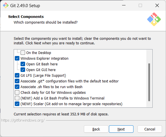
When running Git commands, we recommend Windows users to use the Git Bash terminal that comes with Git. To open Git Bash terminal, hit the key and type git-bash.
It may be possible that the installation didn't add a shortcut to the Start Menu.
You can navigate to the directory where git-bash.exe is (most likely C:\Program Files\Git\git-bash.exe), double click git-bash.exe to open Git Bash.
You can also right-click it and choose Pin to Start or Pin to taskbar.
SIDEBAR: Git Bash Terminal
Git Bash is a terminal application that lets you use Git from the command line on Windows. Since Git was originally developed for Unix-like systems (like Linux and macOS), Windows does not come with a native shell that supports all the commands and utilities commonly used with Git.

Git Bash provides a Unix-like command-line environment on Windows. It includes:
- A Bash shell (Bash stands for Bourne Again SHell), which is a widely used command-line interpreter on Linux and macOS.
- Common Unix tools and commands (like
ls,cat,ssh, etc.) that are useful when working with Git and scripting.
When copy-pasting text onto a Git Bash terminal, you will not be able to use the familiar Ctrl+V key combo to paste. Instead, right-click on the terminal and use the Paste menu option.
Install homebrew if you don't already have it, and then, run brew install git
Use your Linux distribution's package manager to install Git. Examples:
Debian/Ubuntu, run
sudo apt-get updateand thensudo apt-get install git.Fedora: run
sudo dnf updateand thensudo dnf install git.
Verify Git is installed, by running the following command in a terminal.
git --version
git version 2._._
The output should display the version number.
Configuring user.name and user.email
Git needs to know who you are to record changes properly. When you save a snapshot of your work in Git, it records your name and email as the author of that change. This ensures everyone working on the project can see who made which changes. Accordingly, you should set the config settings user.name and user.email before you start Git for revision control.
Interacting with Git: CLI vs GUI
Git is fundamentally a command-line tool. You primarily interact with it through its by typing commands. This gives you full control over its features and helps you understand what’s really happening under the hood.
clients for Git also exist, such as Sourcetree, GitKraken, and the built-in Git support in editors like Intellij IDEA and VS Code. These tools provide a more visual way to perform some Git operations.
If you're new to Git, it's best to learn the CLI first. The CLI is universal, always available (even on servers), and helps you build a solid understanding of Git’s concepts. You can use GUI clients as a supplement — for example, to visualise complex history structures.
Mastering the CLI gives you confidence and flexibility, while GUI tools can serve as helpful companions.
PREPARATION: [Optional] Install a GUI client
Optionally, you can install a Git GUI client. e.g., Sourcetree (installation instructions).
Our Git lessons show how to perform Git operations in Git CLI, and in Sourcetree -- the latter just to illustrate how Git GUIs work. It is perfectly fine for you to learn the CLI only.
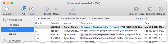
[image credit: https://www.sourcetreeapp.com]
To be able to save snapshots of a folder using Git, you must first put the folder under Git's control by initialising a Git repository in that folder.
Normally, we use Git to manage a revision history of a specific folder, which gives us the ability to revision-control any file in that folder and its subfolders.
To put a folder under the control of Git, we initialise a repository (short name: repo) in that folder. This way, we can initialise repos in different folders, to revision-control different clusters of files independently of each other e.g., files belonging to different projects.
You can follow the hands-on practical below to learn how to initialise a repo in a folder.
What is this? HANDS-ON panels contain hands-on activities you can do as you learn Git. If you are new to Git, we strongly recommend that you do them yourself (even if they appear straightforward), as hands-on usage will help you internalise the concepts and operations better.
1 First, choose a folder. The folder may or may not have any files in it already. For this practical, let us create a folder named things for this purpose.
cd my-projects
mkdir things
2 Then cd into it.
cd things
3 Run the git status command to check the status of the folder.
git status
fatal: not a git repository (or any of the parent directories): .git
Don't panic. The error message is expected. It confirms that the folder currently does not have a Git repo.
4 Now, initialise a repository in that folder.
Use the command git init which should initialise the repo.
git init
Initialized empty Git repository in things/.git/
The output might also contain a hint about a name for an initial branch (e.g., hint: Using 'master' as the name for the initial branch ...). You can ignore that for now.
Note how the output mentions the repo being created in things/.git/ (not things/). More on that later.
Windows: Click
File→Clone/New…→ Click on+ Createbutton on the top menu bar.
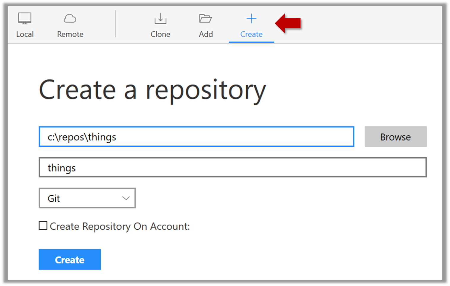
Enter the location of the directory and clickCreate.Mac:
New...→Create Local Repository(orCreate New Repository) → Click...button to select the folder location for the repository → click theCreatebutton.
done!
Initialising a repo results in two things:
- First, Git now recognises this folder as a Git repository, which means it can now help you track the version history of files inside this folder.
To confirm, you can run the git status command. It should respond with something like the following:
git status
On branch master

No commits yet

nothing to commit (create/copy files and use "git add" to track)
Don't worry if you don't understand the output (we will learn about them later); what matters is that it no longer gives an error message as it did before.
done!
- Second, Git created a hidden subfolder named
.gitinside thethingsfolder. This folder will be used by Git to store metadata about this repository.
A Git-controlled folder is divided into two main parts:
- The repository – stored in the hidden
.gitsubfolder, which contains all the metadata and history. - The working directory – everything else in that folder, where you create and edit files.
To save a snapshot, you start by specifying what to include in it, also called staging.
Git considers new files that you add to the working directory as 'untracked' i.e., Git is aware of them, but they are not yet under Git's control. The same applies to files that existed in the working folder at the time you initialised the repo.
A Git repo has an internal space called the staging area which it uses to build the next snapshot. Another name for the staging area is the index.
We can stage an untracked file to tell Git that we want its current version to be included in the next snapshot. Once you stage an untracked file, it becomes 'tracked' (i.e., under Git's control).
In the example below, you can see how staging files change the status of the repo as you go from (a) to (c).
staging area
[empty]
other metadata ...
├─ fruits.txt (untracked!)
└─ colours.txt (untracked!)
(a) State of the repo, just after initialisation, and creating two files. Both are untracked.
staging area
└─ fruits.txt
other metadata ...
├─ fruits.txt (tracked)
└─ colours.txt (untracked!)
(b) State after staging
fruits.txt.staging area
├─ fruits.txt
└─ colours.txt
other metadata ...
├─ fruits.txt (tracked)
└─ colours.txt (tracked)
(c) State after staging
colours.txt.1 First, add a file (e.g., fruits.txt) to the things folder.
Here is an easy way to do that with a single terminal command.
echo -e "apples\nbananas\ncherries\n" > fruits.txt
apples
bananas
cherries
When using the echo command to write to text files from git-bash, you might see a warning LF will be replaced by CRLF the next time Git touches it when Git interacts with such a file. This warning is caused by the way line endings are handled differently by Git and Windows. You can simply ignore it, or suppress it in future by running the following command:
git config --global core.safecrlf false
2 Stage the new file.
2.1 Check the status of the folder using the git status command.
git status
On branch master

No commits yet

Untracked files:
  (use "git add <file>..." to include in what will be committed)

  fruits.txt
nothing added to commit but untracked files present (use "git add" to track)
2.2 Use the add command to stage the file.
git add fruits.txt
You can replace the add with stage (e.g., git stage fruits.txt) and the result is the same (they are synonyms).
2.3 Check the status again. You can see the file is no longer 'untracked'.
git status
On branch master

No commits yet

Changes to be committed:
  (use "git rm --cached <file>..." to unstage)

      new file:   fruits.txt
As before, don't worry if you don't understand the content of the output (we'll unpack it in a later lesson). The point to note is that the file is no longer listed as 'untracked'.
2.1 Note how the file is shown as ‘unstaged’. The question mark icon indicates the file is untracked.
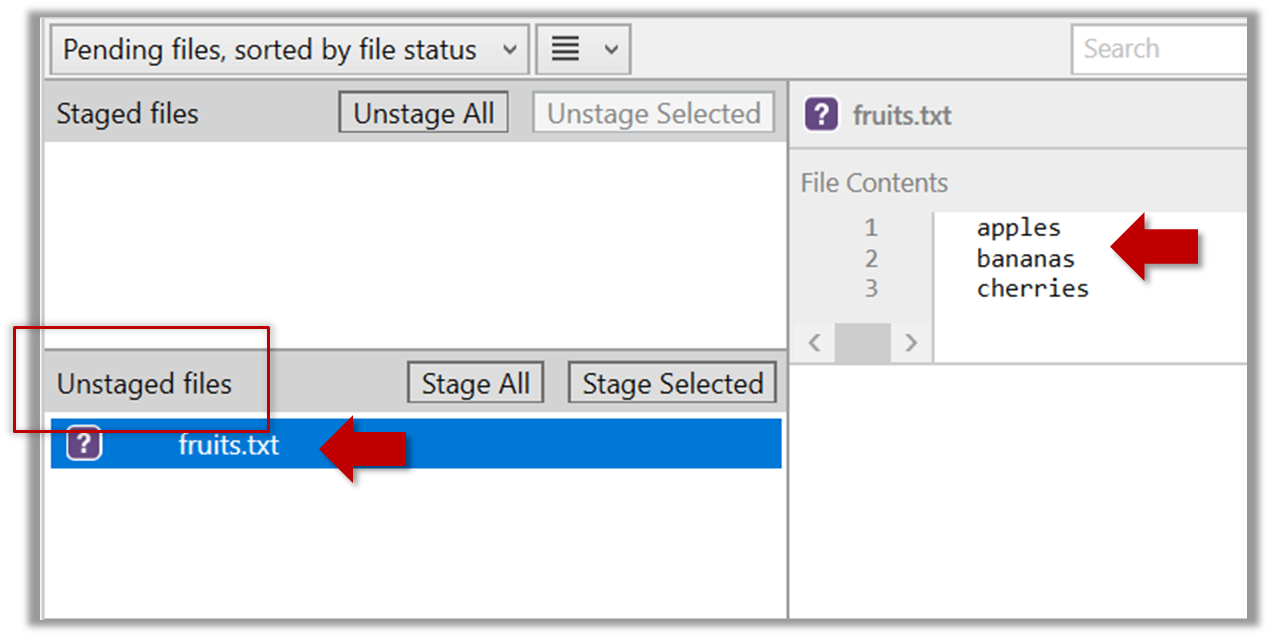
If the newly-added file does not show up in Sourcetree UI, refresh the UI (: F5
| ⌥+R)
2.2 Stage the file:
Select the fruits.txt and click on the Stage Selected button.
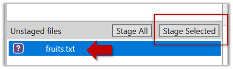
Staging can be done using tick boxes or the ... menu in front of the file.
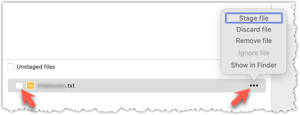
2.3 Note how the file is staged now i.e., fruits.txt appears in the Staged files panel now.
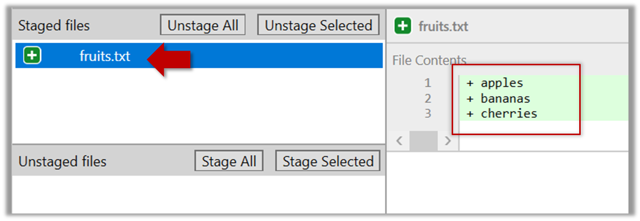
If Sourcetree shows a \ No newline at the end of the file message below the staged lines (i.e., below the cherries line in the above screenshot), that is because you did not hit enter after entering the last line of the file (hence, Git is not sure if that line is complete). To rectify, move the cursor to the end of the last line in that file and hit enter (like you are adding a blank line below it). This new change will now appear as an 'unstaged' change. Stage it as well.
done!
If you modify a staged file, it goes into the 'modified' state i.e., the file contains modifications that are not present in the copy that is waiting (in the staging area) to be included in the next snapshot. If you wish to include these new changes in the next snapshot, you need to stage the file again, which will overwrite the copy of the file that was previously in the staging area.
The example below shows how the status of a file changes when it is modified after it was staged.
staging area
Alice
other metadata ...
Alice
(a) The file names.txt is staged. The copy in the staging area is an exact match to the one in the working directory.
staging area
Alice
other metadata ...
Alice
Bob
(b) State after adding a line to the file. Git indicates it as 'modified' because it now differs from the version in the staged area.
staging area
Alice
Bob
other metadata ...
Alice
Bob
(c) After staging the file again, the staging area is updated with the latest copy of the file, and it is no longer marked as 'modified'.
1 First, add another line to fruits.txt, to make it 'modified'.
Here is a way to do that with a single terminal command.
echo "dragon fruits" >> fruits.txt
apples
bananas
cherries
dragon fruits
2 Now, verify that Git sees that file as 'modified'.
Use the git status command to check the status of the working directory.
$ git status
On branch master

No commits yet

Changes to be committed:
(use "git rm --cached <file>..." to unstage)
new file:   fruits.txt

Changes not staged for commit:
(use "git add <file>..." to update what will be committed)
(use "git restore <file>..." to discard changes in working directory)
modified:   fruits.txt
Note how fruits.txt now appears twice, once as new file: ... (representing the version of the file we staged earlier, which had only three lines) and once as modified: ... (representing the latest version of the file which now has a fourth line).
Note how fruits.txt appears in the Staged files panel as well as 'Unstaged files'.
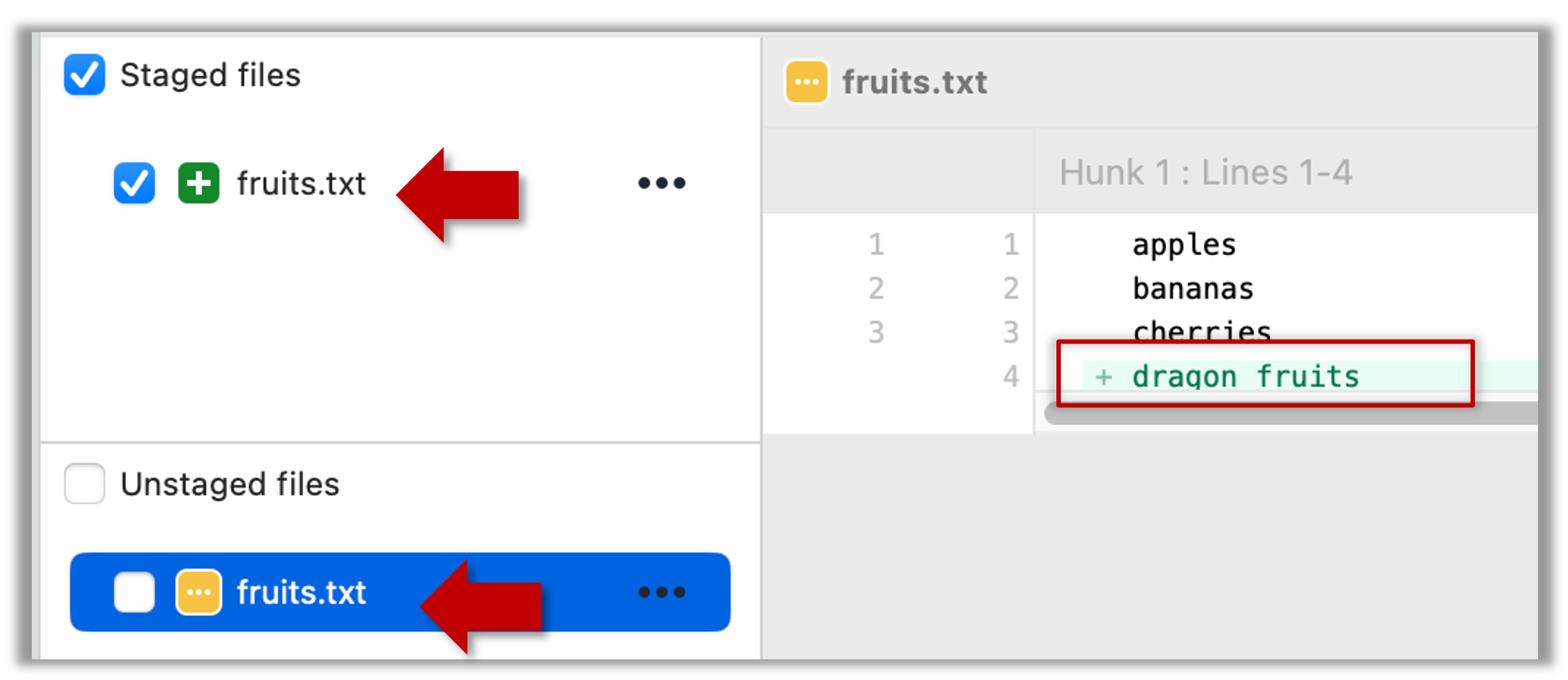
3 Stage the file again, the same way you added/staged it earlier.
4 Verify that Git no longer sees it as 'modified', similar to step 2.
done!
Git does not track empty folders. You can test this by adding an empty subfolder inside the things folder (e.g., things/more-things) and checking if it shows up as 'untracked' (it will not). If you add a file to that folder (e.g., things/more-things/food.txt) and then staged that file (e.g., git add more-things/food.txt), the folder will now be included in the next snapshot.
After staging, you can now proceed to save the snapshot, aka creating a commit.
Saving a snapshot is called committing and a saved snapshot is called a commit.
A Git commit is a full snapshot of your working directory based on the files you have staged, more precisely, a record of the exact state of all files in the staging area (index) at that moment -- even the files that have not changed since the last commit. This is in contrast to other revision control software that only store the in a commit. Consequently, a Git commit has all the information it needs to recreate the snapshot of the working directory at the time the commit was created.
A commit also includes metadata such as the author, date, and an optional commit message describing the change.
A Git commit is a snapshot of all tracked files, not simply a delta of what changed since the last commit.
Assuming you have previously staged changes to the fruits.txt, go ahead and create a commit.
1 First, let us do a sanity check using the git status command.
git status
On branch master

No commits yet

Changes to be committed:
(use "git rm --cached <file>..." to unstage)
  new file:   fruits.txt
2 Now, create a commit using the commit command. The -m switch is used to specify the commit message.
git commit -m "Add fruits.txt"
[master (root-commit) d5f91de] Add fruits.txt
 1 file changed, 5 insertions(+)
 create mode 100644 fruits.txt
3 Verify the staging area is empty using the git status command again.
git status
On branch master
nothing to commit, working tree clean
Note how the output says nothing to commit which means the staging area is now empty.
Click the Commit button, enter a commit message (e.g. add fruits.txt) into the text box, and click Commit.
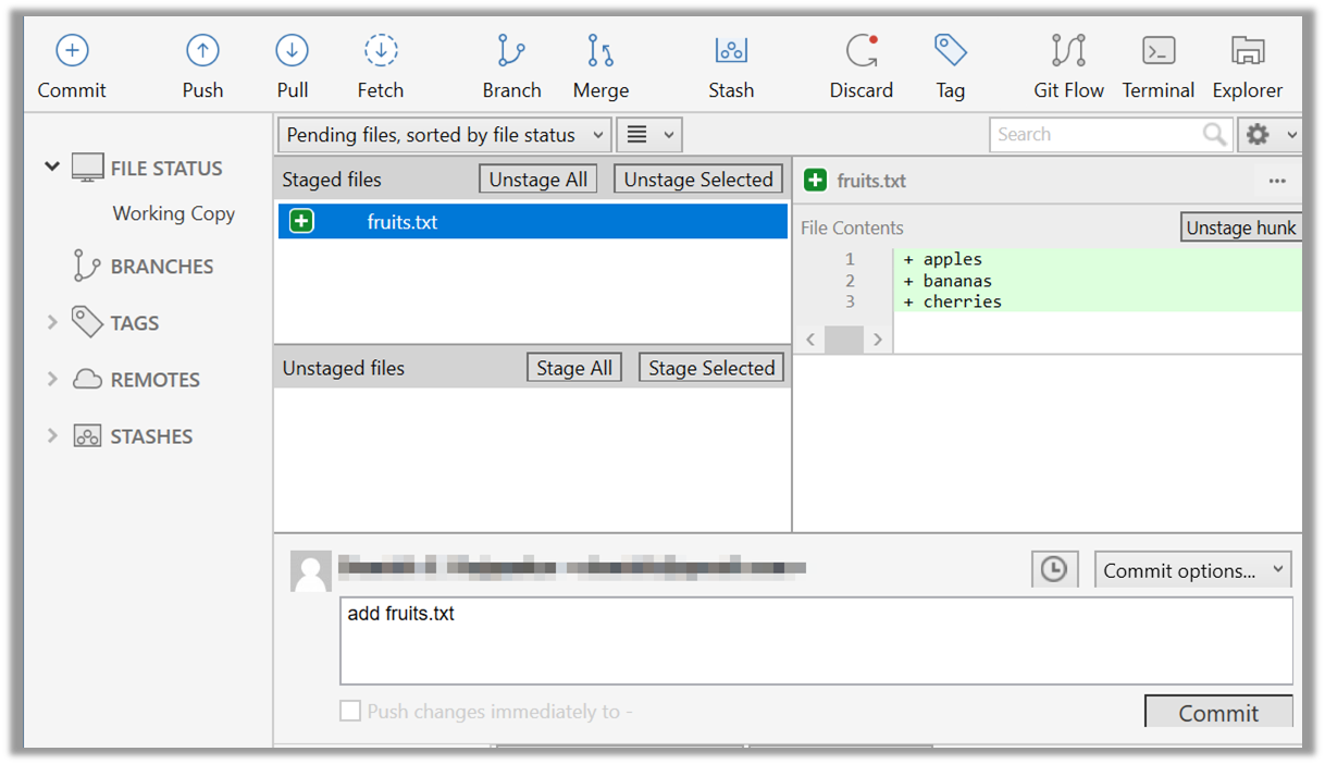
done!
Git commits form a timeline, as each corresponds to a point in time when you asked Git to take a snapshot of your working directory. Each commit links to at least one previous commit, forming a structure that we can traverse.
A timeline of commits is called a branch. By default, Git names the initial branch master -- though many now use main instead. You'll learn more about branches in future lessons. For now, just be aware that the commits you create in a new repo will be on a branch called master (or main) by default.
gitGraph
    %%{init: { 'theme': 'default', 'gitGraph': {'mainBranchName': 'master (or main)'}} }%%
    commit id: "Add fruits.txt"
    commit id: "Update fruits.txt"
    commit id: "Add colours.txt"
    commit id: "..."
Git can show you the list of commits in the Git history.
1 View the list of commits, which should show just the one commit you created just now.
You can use the git log command to see the commit history.
git log
commit d5f91de... (HEAD -> master)
Author: ... <...@...>
Date:   ...

Add fruits.txt
Use the Q key to exit the output screen of the git log command.
Note how the output has some details about the commit you just created. You can ignore most of it for now, but notice it also shows the commit message you provided.
Expand the BRANCHES menu and click on the master to view the history graph, which contains only one node at the moment, representing the commit you just added. For now, ignore the label master attached to the commit.
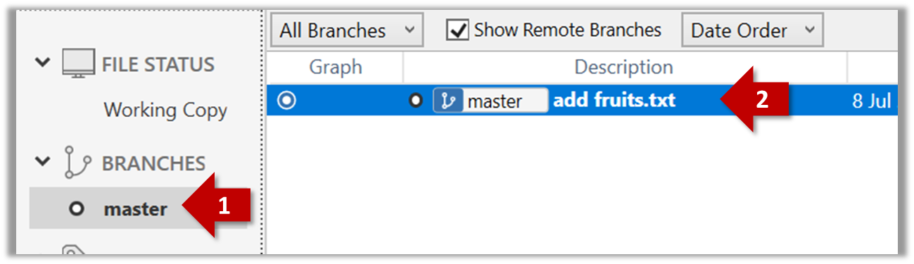
2 Create a few more commits (i.e., a few rounds of add/edit files -> stage -> commit), and observe how the list of commits grows.
Here is an example list of bash commands to add two commits while observing the list of commits
$ echo "figs" >> fruits.txt  # add another line to fruits.txt
$ git add fruits.txt  # stage the updated file
$ git commit -m "Insert figs into fruits.txt"  # commit the changes
$ git log  # check commits list

$ echo "a file for colours" >> colours.txt  # add a colours.txt file
$ echo "a file for shapes" >> shapes.txt  # add a shapes.txt file
$ git add colours.txt shapes.txt  # stage both files in one go
$ git commit -m "Add colours.txt, shapes.txt"  # commit the changes
$ git log  # check commits list
The output of the final git log should be something like this:
commit 18300... (HEAD -> master)
Author: ... <...@...>
Date:   ...

    Add colours.txt, shapes.txt

commit 2beda...
Author: ... <...@...>
Date:   ...

    Insert figs into fruits.txt

commit d5f91...
Author: ... <...@...>
Date:   ...

    Add colours.txt, shapes.txt
To see the list of commits, click on the History item (listed under the WORKSPACE section) on the menu on the right edge of Sourcetree.
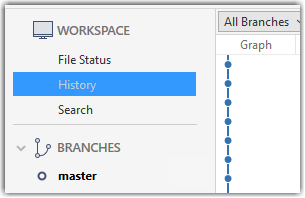
After adding two more commits, the list of commits should look something like this:
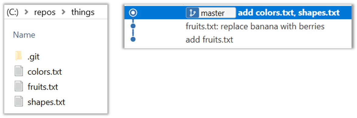
done!
To back up your Git repo on the cloud, you’ll need to use a remote repository service, such as GitHub.
A repo you have on your computer is called a local repo. A remote repo is a repo hosted on a remote computer and allows remote access. Some use cases for remote repositories:
- as a backup of your local repo
- as an intermediary repo to work on the same files from multiple computers
- for sharing the revision history of a codebase among team members of a multi-person project
It is possible to set up a Git remote repo on your own server, but an easier option is to use a remote repo hosting service such as GitHub.
To use GitHub, you need to sign up for an account, and configure related tools/settings first.
GitHub is a web-based service that hosts Git repositories and adds collaboration features on top of Git. Two other similar platforms are GitLab and Bitbucket. While Git manages version control locally, such platforms make it easier for individuals and teams to work together by providing shared access to repositories, issue tracking, pull requests, and permission controls. They are widely used in both open-source and commercial software development. Here we'll be using GitHub.
On GitHub, a Git repo can be put in one of two spaces:
- A GitHub user account represents an individual user. It is created when you sign up for GitHub and includes a username, profile page, and personal settings. With a user account, you can create your own repositories, contribute to others’ projects, and manage collaboration settings for any repositories you own.
- A GitHub organisation (org for short) is a shared account used by a group such as a team, company, or open-source project. Organisations can own repositories and manage access to them through teams, roles, and permissions. Organisations are especially useful when managing repositories with shared ownership or when working at scale.
Every GitHub user must have a user account, even if they primarily work within an organisation.
Before you can interact with GitHub from your local Git client, you need to set up authentication. In the past, you could simply enter your GitHub username and password, but GitHub no longer accepts passwords for Git operations. Instead, you’ll use a more secure method — such as a Personal Access Token (PAT) or SSH keys — to prove your identity.
A Personal Access Token (PAT) is essentially a long, random string that acts like a password, but it can be scoped to specific permissions (e.g., read-only or full access) and revoked at any time. This makes it more secure and flexible than a traditional password.
Git supports two main protocols for communicating with GitHub: HTTPS and SSH.
- With HTTPS, you connect over the web and authenticate using your GitHub username and a Personal Access Token.
- With SSH, you connect using a cryptographic key pair you generate on your machine. Once you add your public key to your GitHub account, GitHub recognises your machine and lets you authenticate without typing anything further.
GitHub associates a commit to a user based on the email address in the commit metadata. When you push a commit, GitHub checks if the email matches a verified email on a GitHub account. If it does, the commit is shown as authored by that user. If the email doesn’t match any account, the commit is still accepted but won’t be linked to any profile.
GitHub provides a no-reply email (e.g., 12345678+username@users.noreply.github.com) that you can use as your Git user.email to hide your real email while still associating commits with your GitHub account.
PREPARATION: [Optional] Configure user.email to use the no-reply email from GitHub
If you prefer not to include your real email address in commits, you can do the following:
Find your no-reply email provided by GitHub: Navigate to the email settings of your GitHub account and select the option to
Keep my email address private. The no-reply address will then be displayed, typically in the formatID+USERNAME@users.noreply.github.com.
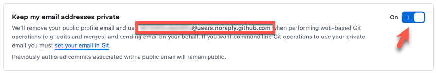
Update your
user.emailwith that email address e.g.,git config --global user.email "12345678+username@users.noreply.github.com"
GitHub offers its own clients to make working with GitHub more convenient.
- The GitHub Desktop app provides a GUI for performing GitHub operations from your desktop, without needing to visit the GitHub web UI.
- The GitHub CLI (
gh) brings GitHub-specific commands to your terminal, letting you perform operations on GitHub from your commandline.
The first step of backing up a local repo on GitHub: create an empty repository on GitHub.
You can create a remote repository based on an existing local repository, to serve as a remote copy of your local repo. For example, suppose you created a local repo and worked with it for a while, but now you want to upload it onto GitHub. The first step is to create an empty repository on GitHub.
1 Login to your GitHub account and choose to create a new repo.
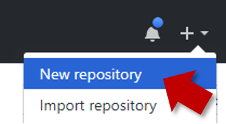
2 In the next screen, provide a name for your repo but keep the Initialize this repo ... tick box unchecked.
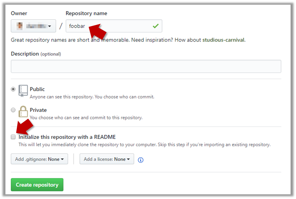
3 Note the URL of the repo. It will be of the form
https://github.com/{your_user_name}/{repo_name}.git.
e.g., https://github.com/johndoe/foobar.git (note the .git at the end)
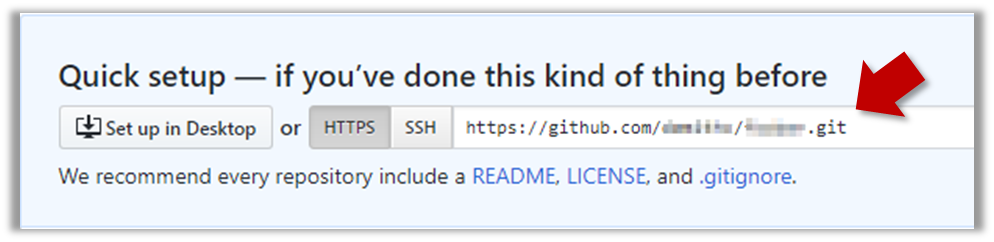
done!
The second step of backing up a local repo on GitHub: link the local repo with the remote repo on GitHub.
A Git remote is a reference to a repository hosted elsewhere, usually on a server like GitHub, GitLab, or Bitbucket. It allows your local Git repo to communicate with another remote copy — for example, to upload locally-created commits that are missing in the remote copy.
By adding a remote, you are informing the local repo details of a remote repo it can communicate with, for example, where the repo exists and what name to use to refer to the remote.
The URL you use to connect to a remote repo depends on the protocol — HTTPS or SSH:
- HTTPS URLs use the standard web protocol and start with
https://github.com/(for GitHub users). e.g.,https://github.com/username/repo-name.git - SSH URLs use the secure shell protocol and start with
git@github.com:. e.g.,git@github.com:username/repo-name.git
A Git repo can have multiple remotes. You simply need to specify different names for each remote (e.g., upstream, central, production, other-backup ...).
Add the empty remote repo you created on GitHub as a remote of a local repo you have.
1 In a terminal, navigate to the folder containing the local repo things your created earlier.
2 List the current list of remotes using the git remote -v command, for a sanity check. No output is expected if there are no remotes yet.
3 Add a new remote repo using the git remote add <remote-name> <remote-url> command.
i.e., if using HTTPS, git remote add origin https://github.com/{YOUR-GITHUB-USERNAME}/things.git
4 List the remotes again to verify the new remote was added.
git remote -v
origin  https://github.com/johndoe/things.git (fetch)
origin  https://github.com/johndoe/things.git (push)
The same remote will be listed twice, to show that you can do two operations (fetch and push) using this remote. You can ignore that for now. The important thing is the remote you added is being listed.
1 Open the local repo in Sourcetree.
2 Choose Repository → Repository Settings menu option.
3 Add a new remote to the repo with the following values.
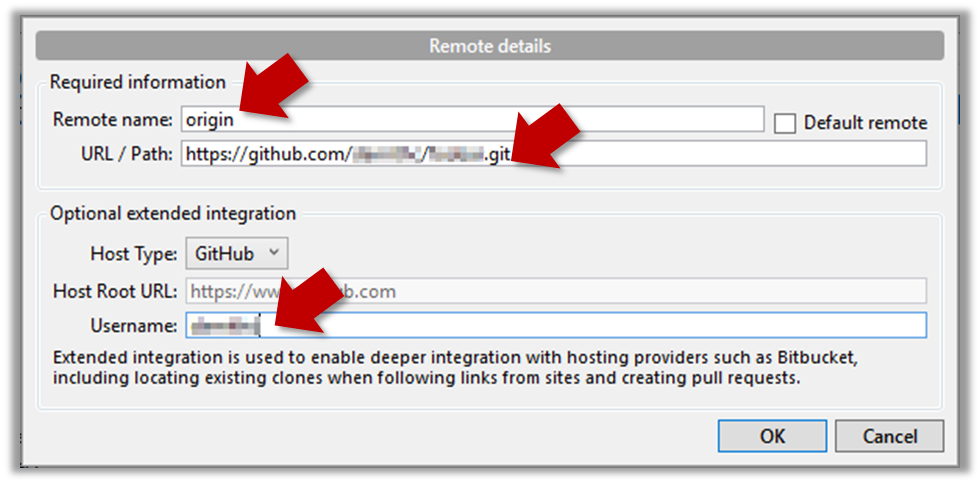
Remote name: the name you want to assign to the remote repo i.e.,originURL/path: the URL of your remote repo
i.e.,https://github.com/{YOUR-GITHUB-USERNAME}/things.gitUsername: your GitHub username
4 Verify the remote was added by going to Repository → Repository Settings again.
5 Add another remote, to verify that a repo can have multiple remotes. You can use any name (e.g., backup and any URL for this).
done!
The third step of backing up a local repo on GitHub: push a copy of the local repo to the remote repo.
You can push content of one repository to another. Pushing can transfer Git history (e.g., past commits) as well as files in the working directory. Note that pushing to a remote repo requires you to have write-access to it.
When pushing to a remote repo, you typically need to specify the following information:
- The name of the remote (e.g.,
origin). - The name of your current local branch (e.g.,
master).
If this is the first time you are pushing this branch to the remote repo, you can also ask Git to track this remote/branch pairing (e.g., remember that this local master branch is tracking the master branch in the repo origin i.e., local master branch is tracking upstream origin/master branch), so in future you can push the same remote/branch without needing to specify them again.
Here, we assume you already have a local repo that is connected to an empty remote repo, from previous hands-on practicals:
# format: git push -u <remote-repo-name> <branch-name>
git push -u origin master
Explanation:
push: the Git sub-command that pushes the current local repo content to a remote repoorigin: name of the remotemaster: branch to push-u(or--set-upstream): the flag that tells Git to track that this localmasteris trackingorigin/masterbranch
Click the Push button on the buttons ribbon at the top.

In the next dialog, ensure the settings are as follows, ensure the Track option is selected, and click the Push button on the dialog.
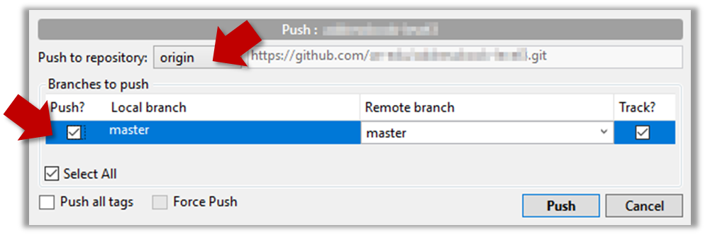
done!
The push command can be used repeatedly to send further updates to another repo e.g., to update the remote with commits you created since you pushed the first time.
Add a few more commits to your local repo, and push those commits to the remote repo, as follows:
1 Commit some changes in your local repo.
Use the git commit command to create commits, as you did before.
Optionally, you can run the git status command, which should confirm that your local branch is 'ahead' by one commit (i.e., the local branch has one new commit that is not in the corresponding branch in the remote repo).
git status
On branch master
Your branch is ahead of 'origin/master' by 1 commit.
  (use "git push" to publish your local commits)

nothing to commit, working tree clean
Create commits as you did before.
Before pushing the new commit, Sourcetree will indicate that your local branch is 'ahead' by one commit (i.e., the local branch has one new commit that is not in the corresponding branch in the remote repo).

2 Push the new commits to your fork on GitHub.
To push the newer commit(s) to the remote, any of the following commands should work:
git push origin mastergit push origin
(due to tracking you set up earlier, Git will assume you are pushing themasterbranch)git push
(due to tracking, Git will assume you are pushing to the remoteoriginand to the branchmasteri.e.,origin/master)
To push, click the Push button on the top buttons ribbon, ensure the settings are as follows in the next dialog, and click the Push button on the dialog.
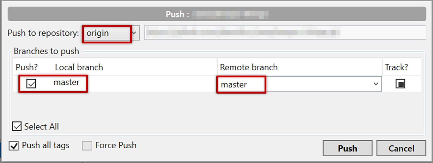
done!
Note that you can push between two repos only if those repos have a shared history among them (i.e., one should have been created by copying the other).
Git allows you to specify which files should be omitted from revision control.
You can specify which files Git should ignore from revision control. While you can always omit files from revision control simply by not staging them, having an 'ignore-list' is more convenient, especially if there are files inside the working folder that are not suitable for revision control (e.g., temporary log files) or files you want to prevent from accidentally including in a commit (files containing confidential information).
A repo-specific ignore-list of files can be specified in a .gitignore file, stored in the root of the repo folder.
The .gitignore file itself can be either revision controlled or ignored.
- To version control it (the more common choice – which allows you to track how the
.gitignorefile changes over time), simply commit it as you would commit any other file. - To ignore it, simply add its name to the
.gitignorefile itself.
The .gitignore file supports file patterns e.g., adding temp/*.tmp to the .gitignore file prevents Git from tracking any .tmp files in the temp directory.
SIDEBAR: .gitignore File Syntax
Blank lines: Ignored and can be used for spacing.
Comments: Begin with
#(lines starting with # are ignored).# This is a commentWrite the name or pattern of files/directories to ignore.
log.txt # Ignores a file named log.txtWildcards:
*matches any number of characters, except/(i.e., for matching a string within a single directory level):abc/*.tmp # Ignores all .tmp files in abc directory**matches any number of characters (including/)**/foo.tmp # Ignores all foo.tmp files in any directory?matches a single characterconfig?.yml # Ignores config1.yml, configA.yml, etc.[abc]matches a single character (a, b, or c)file[123].txt # Ignores file1.txt, file2.txt, file3.txt
Directories:
- Add a trailing
/to match directories.logs/ # Ignores the logs directory - Patterns without
/match files/folders recursively.*.bak # Ignores all .bak files anywhere - Patterns with
/are relative to the.gitignorelocation./secret.txt # Only ignores secret.txt in the root directory
- Add a trailing
Negation: Use
!at the start of a line to not ignore something.*.log # Ignores all .log files !important.log # Except important.log
Example:
# Ignore all log files
*.log

# Ignore node_modules folder
node_modules/

# Don’t ignore main.log
!main.log
1 Add a file into your repo's working folder that you presumably do not want to revision-control e.g., a file named temp.txt. Observe how Git has detected the new file.
Add a few other files with .tmp extension.
2 Configure Git to ignore those files:
Create a file named .gitignore in the working directory root and add the following line in it.
temp.txt
Observe how temp.txt is no longer detected as 'untracked' by running the git status command (but now it will detect the .gitignore file as 'untracked'.
Update the .gitignore file as follows:
temp.txt
*.tmp
Observe how .tmp files are no longer detected as 'untracked' by running the git status command.
The file should be currently listed under Unstaged files. Right-click it and choose Ignore.... Choose Ignore exact filename(s) and click OK.
Also take note of other options available e.g., Ignore all files with this extension etc. They may be useful in future.
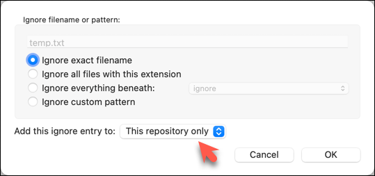
Note how the temp.text is no longer listed under Unstaged files. Observe that a file named .gitignore has been created in the working directory root and has the following line in it. This new file is now listed under Unstaged files.
temp.txt
Right-click on any of the .tmp files you added, and choose Ignore... as you did previously. This time, choose the option Ignore files with this extension.
Note how .temp files are no longer shown as unstaged files, and the .gitignore file has been updated as given below:
temp.txt
*.tmp
3 Optionally, stage and commit the .gitignore file.
done!
Files recommended to be omitted from version control
- Binary files generated when building your project e.g.,
*.class,*.jar,*.exe(reasons: 1. no need to version control these files as they can be generated again from the source code 2. Revision control systems are optimized for tracking text-based files, not binary files. - Temporary files e.g., log files generated while testing the product
- Local files i.e., files specific to your own computer e.g., local settings of your IDE
- Sensitive content i.e., files containing sensitive/personal information e.g., credential files, personal identification data (especially, if there is a possibility of those files getting leaked via the revision control system).
GitHub allows you to create a remote copy of another remote repo, called forking.
A fork is a copy of a remote repository created on the same hosting service such as GitHub, GitLab, or Bitbucket. On GitHub, you can fork a repository from another user or organisation into your own space (i.e., your user account or an organisation you have sufficient access to). Forking is particularly useful if you want to experiment with a repo but don’t have write permissions to the original -- you can fork it and work on your own remote copy without affecting the original repository.
0 Create a GitHub account if you don't have one yet.
1 Go to the GitHub repo you want to fork e.g., samplerepo-things
2 Click on the  button in the top-right corner. In the next step,
- choose to fork to your own account or to another GitHub organization that you are an admin of.
- un-tick the
[ ] Copy the master branch onlyoption, so that you get copies of other branches (if any) in the repo.
done!
Forking is not a Git feature, but a feature provided by hosted Git services like GitHub, GitLab, or Bitbucket.
GitHub does not allow you to fork the same repo more than once to the same destination. If you want to re-fork, you need to delete the previous fork.
The next step is to create a local copy of the remote repo, by cloning the remote repo.
You can clone a repository to create a full copy of it on your computer. This copy includes the entire revision history, branches, and files of the original, so it behaves just like the original repository. For example, you can clone a repository from a hosting service like GitHub to your computer, giving you a complete local version to work with.
Cloning a repo automatically creates a remote named origin which points to the repo you cloned from.
The repo you cloned from is often referred to as the upstream repo.
1 Clone the remote repo to your computer. For example, you can clone the samplerepo-things repo, or the fork your created from it in a previous lesson.
Note that the URL of the GitHub project is different from the URL you need to clone a repo in that GitHub project. e.g.
https://github.com/se-edu/samplerepo-things  # GitHub project URL
https://github.com/se-edu/samplerepo-things.git # the repo URL
You can use the git clone <repository-url> [directory-name] command to clone a repo.
<repository-url>: The URL of the remote repository you want to copy.[directory-name](optional): The name of the folder where you want the repository to be cloned. If you omit this, Git will create a folder with the same name as the repository.
git clone https://github.com/se-edu/samplerepo-things.git  # if using HTTPS
git clone git@github.com:se-edu/samplerepo-things.git  # if using SSH

git clone https://github.com/foo/bar.git my-bar-copy  # also specifies a dir to use
For exact steps for cloning a repo from GitHub, refer to this GitHub document.
File → Clone / New ... and provide the URL of the repo and the destination directory.
File → New ... → Choose as shown below → Provide the URL of the repo and the destination directory in the next dialog.
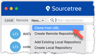
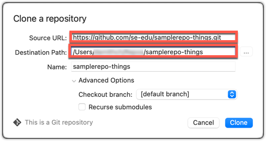
2 Verify the clone has a remote named origin pointing to the upstream repo.
Use the git remote -v command that you learned earlier.
Choose Repository → Repository Settings menu option.
done!
When there are new changes in the remote, you need to pull those changes down to your local repo.
There are two steps to bringing down changes from a remote repository into a local repository: fetch and merge.
- Fetch is the act of downloading the latest changes from the remote repository, but without applying them to your current branch yet. It updates metadata in your repo so that repo knows what has changed in the remote repo, but your own local branch remain untouched.
- Merge is what you do after fetching, to actually incorporate the fetched changes into your local branch. It combines your local branch with the changes from the corresponding branch from the remote repo.
1 Clone the repo se-edu/samplerepo-finances. It has 3 commits. Your clone now has a remote origin pointing to the remote repo you cloned from.
2 Change the remote origin to point to samplerepo-finances-2. This remote repo is a copy of the one you cloned, but it has two extra commits.
git remote set-url origin https://github.com/se-edu/samplerepo-finances-2.git
Go to Repository → Repository settings ... to update remotes.
3 Verify the local repo is unaware of the extra commits in the remote.
git status
On branch master
Your branch is up to date with 'origin/master'.

nothing to commit, working tree clean
The revision graph should look like the below:

If it looks like the below, it is possible that Sourcetree is auto-fetching data from the repo periodically.
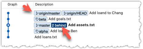
3 Fetch from the new remote.
Use the git fetch <remote> command to fetch changes from a remote. If the <remote> is not specified, the default remote origin will be used.
git fetch origin
remote: Enumerating objects: 8, done.
... # more output ...
   afbe966..cc6a151  master     -> origin/master
 * [new tag]         beta       -> beta
Click on the Fetch button on the top menu:
4 Verify the fetch worked i.e., the local repo is now aware of the two missing commits. Also observe how the local branch ref of the master branch, the staging area, and the working directory remain unchanged after the fetch.
Use the git status command to confirm the repo now knows that it is behind the remote repo.
git status
On branch master
Your branch is behind 'origin/master' by 2 commits, and can be fast-forwarded.
  (use "git pull" to update your local branch)

nothing to commit, working tree clean
Now, the revision graph should look something like the below. Note how the origin/master ref is now two commits ahead of the master ref.
5 Merge the fetched changes.
Use the git merge <remote-tracking-branch> command to merge the fetched changes. Check the status and the revision graph to verify the branch tip has now moved by two more commits.
git merge origin/master

git status
git log --oneline --decorate
To merge the fetched changes, right-click on the latest commit on origin/remote branch and choose Merge.
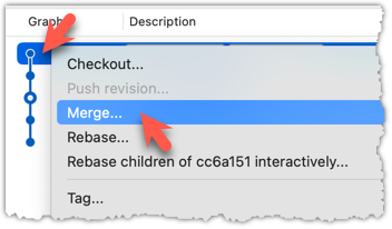
In the next dialog, choose as follows:
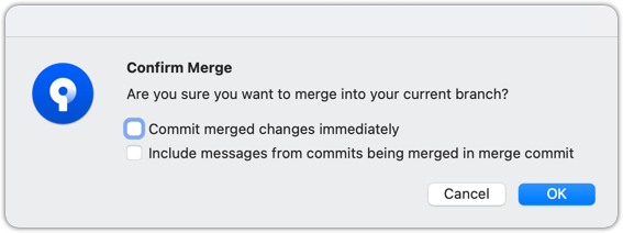
The final result should be something like the below (same as the repo state before we started this hands-on practical):
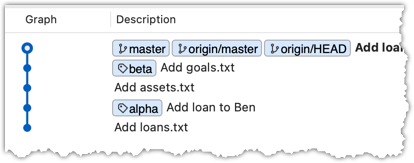
Note that merging the fetched changes can get complicated if there are multiple branches or the commits in the local repo conflict with commits in the remote repo. We will address them when we learn more about Git branches, in a later lesson.
done!
Pull is a shortcut that combines fetch and merge — it fetches the latest changes from the remote and immediately merges them into your current branch. In practice, Git users typically use the pull instead of the fetch-then-merge.
pull = fetch + merge
1 Similar to the previous hands-on practical, clone the repo se-edu/samplerepo-finances (to a new location).
Change the remote origin to point to samplerepo-finances-2.
2 Pull the newer commits from the remote, instead of a fetch-then-merge.
Use the git pull <remote> <branch> command to pull changes.
git pull origin master
The following works too. If the <remote> and <branch> are not specified, Git will pull to the current branch from the remote branch it is tracking.
git pull
Click on the Pull button on the top menu:
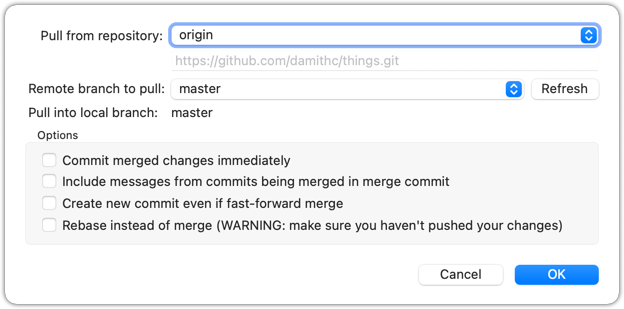
3 Verify the outcome is same as the fetch + merge steps you did in the previous hands-on practical.
done!
You can pull from any number of remote repos, provided the repos involved have a shared history. This can be useful when the upstream repo you forked from has some new commits that you wish to bring over to your copies of the repo (i.e., your fork and your local repo).
Fork se-edu/samplerepo-finances to your GitHub account.
Clone your fork to your computer.
Now, let's pretend that there are some new commits in upstream repo that you would like to bring over to your fork, and your local repo. Here are the steps:
1 Add the upstream repo se-edu/samplerepo-finances as remote named upstream in your local repo.
2 Pull from the upstream repo. If there are new commits (in this case, there will be none), those will come over to your local repo. For example:
git pull upstream master
.3 Push to your fork. Any new commits you pulled from the upstream repo will now appear in your fork as well. For example:
git push origin master
The method given above is the more 'standard' method of synchronising a fork with the upstream repo. In addition, platforms such as GitHub can provide other ways (example: GitHub's Sync fork feature).
4 For good measure, let's pull from another repo.
- Add the upstream repo se-edu/samplerepo-finances-2 as remote named
other-upstreamin your local repo. - Pull from it to your local repo; this will bring some new commits.
- Now, you can push those new commits to your fork.
git remote add other-upstream https://github.com/se-edu/samplerepo-finances-2.git
git pull other-upstream master
git push origin master
done!
It is useful to be able to visualise the commits timeline, aka the revision graph.
The Git data model consists of two types of entities: objects and refs (short for references). In this lesson, you will encounter examples of both.
A Git revision graph is visualisation of a repo's revision history, contains examples of both objects and refs. First, let us learn to work with simpler revision graphs consisting of one branch, such as the one given below.
Nodes in the revision graph represent commits.
- A commit is one of four main types of Git objects (blobs, trees, and annotated tags are the other three, to be covered later).
- A commit identified by its SHA value. A SHA (Secure Hash Algorithm) value is a unique identifier generated by Git to represent each commit. It is produced by using SHA-1 (i.e., one of the algorithms in the SHA family of cryptographic hash functions) on the entire content of the commit. It's a 40-character hexadecimal string (e.g.,
f761ea63738a67258628e9e54095b88ea67d95e2) that acts like a fingerprint, ensuring that every commit can be referenced unambiguously. - A commit is a full snapshot of the working directory, constructed based on the previous commit, and the changes staged. The previous commit a commit is based on is called the parent commit (some commits can have multiple parent commits -- we’ll cover that later).
Edges in the revision graph represent links between a commit and its parent commit(s) In some revision graph visualisations, you might see arrows (instead of lines) showing how each commit points to its parent commit.
Git uses refs to name and keep track of various points in a repository’s history. These refs are essentially 'named-pointers' that can serve as bookmarks to reach a certain point in the revision graph using the ref name.
In the revision graph above, there are two refs master and ←HEAD.
- master is a branch ref. A branch points to the latest commit on a branch (in this visualisation, the commit shown alongside the ref is the one it points to i.e.,
C3). When you create a new commit, the ref of the branch moves to the new commit. - ←HEAD is a special ref. Normally, it points to the current branch (in this example, it is pointing to the
masterbranch), and moves together with the branch ref.
In the revision graph above you see a third type of ref ( origin/master). This is a remote-tracking branch ref that represents the state of a corresponding branch in a remote repository (if you previously set up the branch to 'track' a remote branch). In this example, the master branch in the remote origin is also at the commit C3 (which means you have not created new commits after you pushed to the remote).
If you now create a new commit C4, the state of the revision graph will be as follows:
Explanation: When you create C4, the current branch master moves to C4, and HEAD moves along with it. However, the master branch in the remote origin remains at C3 (because you have not pushed C4 yet). The origin/master ref will move to C4 after you push your repo to the remote again.
Use Git features to examine the revision graph of a simple repo. For this, use a repo with just a few commits and only one branch for this hands-on practical.
1 First, use a simple git log to view the list of commits.
git log
commit f761ea63738a... (HEAD -> master, origin/master)
Author: ... <...@...>
Date:   Sat ...

    Add colours.txt, shapes.txt

commit 2bedace69990...
Author: ... <...@...>
Date:   Sat ...

    Add figs to fruits.txt

commit d5f91de5f0b5...
Author: ... <...@...>
Date:   Fri ...

    Add fruits.txt
For comparison, given below the visual representation of the same revision graph. As you can see, the log output shows the refs slightly differently, but it is not hard to see what they mean.
SIDEBAR: Working with the 'less' pager
Some Git commands — such as git log— may show their output through a pager. A pager is a program that lets you view long text one screen at a time, so you don’t miss anything that scrolls off the top. For example, the output of git log command will temporarily hide the current content of the terminal, and enter the pager view that shows output one screen at a time. When you exit the pager, the git log output will disappear from view, and the previous content of the pager will reappear.
command 1
output 1

git log
→
commit f761ea63738a...
Author: ... <...@...>
Date:   Sat ...

    Add colours.txt
By default, Git uses a pager called less. Given below are some useful commands you can use inside the less pager.
| Command | Description |
|---|---|
q | Quit less and return to the terminal |
↓ or j | Move down one line |
↑ or k | Move up one line |
Space | Move down one screen |
b | Move up one screen |
G | Go to the end of the content |
g | Go to the beginning of the content |
/pattern | Search forward for pattern (e.g., /fix) |
n | Repeat the last search (forward) |
N | Repeat the last search (backward) |
h | Show help screen with all less commands |
If you’d rather see the output directly, without using a pager, you can add the --no-pager flag to the command e.g.,
git --no-pager log
It is possible to ask Git to not use less at all, use a different pager, or fine-tune how less is used. For example, you can reduce Git's use of the pager (recommended), using the following command:
git config --global core.pager "less -FRX"
Explanation:
-F: Quit if the output fits on one screen (don’t show pager unnecessarily)-R: Show raw control characters (for coloured Git output)-X: Keep content visible after quitting the pager (so output stays on the terminal)
2 Use the --oneline flag to get a more concise view. Note how the commit SHA has been truncated to first seven characters (first seven characters of a commit SHA is enough for Git to identify a commit).
git log --oneline
f761ea6 (HEAD -> master, origin/master) Add colours.txt, shapes.txt
2bedace Add figs to fruits.txt
d5f91de Add fruits.txt
3 The --graph flag makes the result closer to a graphical revision graph. Note the * that indicates a node in a revision graph.
git log --oneline --graph
* f761ea6 (HEAD -> master, origin/master) Add colours.txt, shapes.txt
* 2bedace Add figs to fruits.txt
* d5f91de Add fruits.txt
The --graph option is more useful when examining a more complicated revision graph consisting of multiple parallel branches.
Click the History to see the revision graph.
- In some versions of Sourcetree, the
HEADref may not be shown -- it is implied that theHEADref is pointing to the same commit the currently active branch ref is pointing. - If the remote-tracking branch ref (e.g.,
origin/master) is not showing up, you may need to enable theShow Remote Branchesoption.
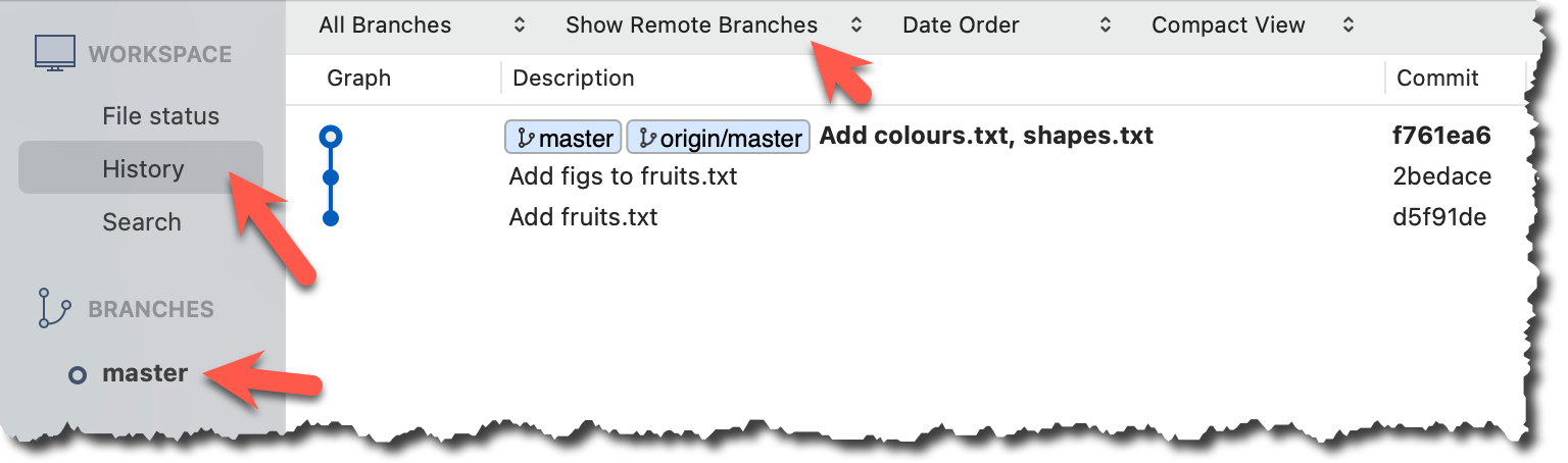
Observe how the revision graph changes as you add a commit, and push that commit to the remote repo.
For example, we can update the fruits.txt in the things repo as follows, and commit it with the message Update fruits list.
apples
bananas
cherries
dragon fruits
elderberries
figs
→
[update file as...]
apples, apricots
bananas
blueberries
cherries
dragon fruits
figs
After creating the new commit, the output of git log --oneline --decorate should be of the form:
e60deae (HEAD -> master) Update fruits list
f761ea6 (origin/master) Add colours.txt, shapes.txt
2bedace Add figs to fruits.txt
d5f91de Add fruits.txt
After pushing the new commit to the remote, the remote-tracking branch ref should move to the new commit:
e60deae (HEAD -> master, origin/master) Update fruits list
f761ea6 Add colours.txt, shapes.txt
2bedace Add figs to fruits.txt
d5f91de Add fruits.txt
After creating the new commit, the branch ref (master) will move to the new commit, but the remote-tracking branch ref (origin/master) will remain at the previous commit. Sourcetree will also indicate that your local branch is 1 commit ahead (i.e., has one more commit than) the remote-tracking branch.
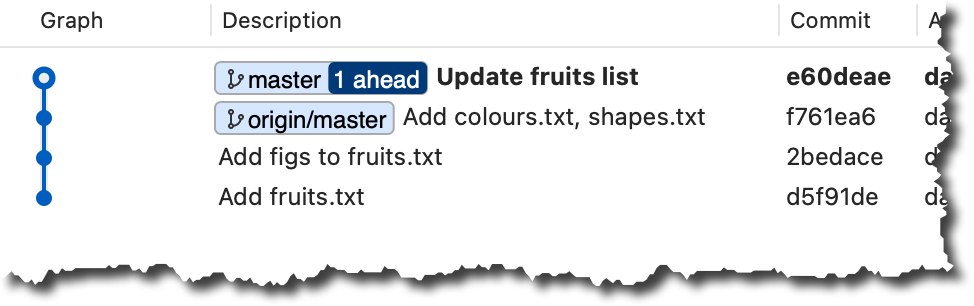
After pushing the new commit to the remote, the remote-tracking branch ref should move to the new commit:
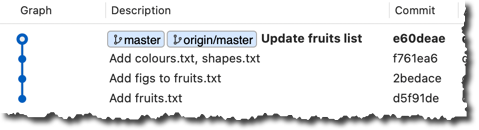
done!
It is also useful to be able to see what changes were included in a specific commit.
When you examine a commit, normally what you see is the 'changes since the previous commit'. This should not be interpreted as Git commits contain only the changes. As you recall, a Git commit contains a full snapshot of the working directory. However, tools used to examine commits show only the changes, as that is the more informative part.
Git shows changes included in a commit by dynamically calculating the difference between the snapshots stored in the target commit and the parent commit. This is because Git commits stores snapshots of the working directory, not changes themselves.
To address a specific commit, you can use its SHA (e.g., e60deaeb2964bf2ebc907b7416efc890c9d4914b). In fact, just the first few characters of the SHA is enough to uniquely address a commit (e.g., e60deae), provided the partial SHA is long enough uniquely identify the commit (i.e., only one commit has that partial SHA).
Naturally, a commit can be addressed using any ref pointing to it too (e.g., HEAD, master).
Another related technique is to use the <ref>~<n> notation (e.g., HEAD~1) to address the commit that is n commits prior to the commit pointed by <ref> i.e., "start with the commit pointed by <ref> and go back n commits".
A further shortcut of this notation is to use HEAD~, HEAD~~, HEAD~~~, ... to mean HEAD~1, HEAD~2, HEAD~3 etc.
HEAD or masterHEAD~1 or master~1 or HEAD~ or master~HEAD~2 or master~2Git uses the diff format to show file changes in a commit. The diff format was originally developed for Unix, later extended with headers and metadata to show changes between file versions and commits. Here is an example diff showing the changes to a file.
diff --git a/fruits.txt b/fruits.txt
index 7d0a594..f84d1c9 100644
--- a/fruits.txt
+++ b/fruits.txt
@@ -1,6 +1,6 @@
-apples
+apples, apricots
 bananas
 cherries
 dragon fruits
-elderberries
 figs
@@ -20,2 +20,3 @@
 oranges
+pears
 raisins
diff --git a/colours.txt b/colours.txt
new file mode 100644
index 0000000..55c8449
--- /dev/null
+++ b/colours.txt
@@ -0,0 +1 @@
+a file for colours
A Git diff can consist of multiple file diffs, one for each changed file. Each file diff can contain one or more hunk i.e., a localised group of changes within the file — including lines added, removed, or left unchanged (included for context).
Given below is how the above diff is divided into its components:
File diff for fruits.txt:
diff --git a/fruits.txt b/fruits.txt
index 7d0a594..f84d1c9 100644
--- a/fruits.txt
+++ b/fruits.txt
Hunk 1:
@@ -1,6 +1,6 @@
-apples
+apples, apricots
 bananas
 cherries
 dragon fruits
-elderberries
 figs
Hunk 2:
@@ -20,2 +20,3 @@
 oranges
+pears
 raisins
File diff for colours.txt:
diff --git a/colours.txt b/colours.txt
new file mode 100644
index 0000000..55c8449
--- /dev/null
+++ b/colours.txt
Hunk 1:
@@ -0,0 +1 @@
+a file for colours
Here is an explanation of the diff:
| Part of Diff | Explanation |
|---|---|
diff --git a/fruits.txt b/fruits.txt | The diff header, indicating that it is comparing the file fruits.txt between two versions: the old (a/) and new (b/). |
index 7d0a594..f84d1c9 100644 | Shows the before and after the change, and the file mode (100 means a regular file, 644 are file permission indicators). |
--- a/fruits.txt+++ b/fruits.txt | Marks the old version of the file (a/fruits.txt) and the new version of the file (b/fruits.txt). |
| This hunk header shows that lines 1-6 (i.e., starting at line 1, showing 6 lines) in the old file were compared with lines 1–6 in the new file. |
-apples+apples, apricots | Removed line apples and added line apples, apricots. |
bananascherriesdragon fruits | Unchanged lines, shown for context. |
-elderberries | Removed line: elderberries. |
figs | Unchanged line, shown for context. |
| Hunk header showing that lines 20-21 in the old file were compared with lines 20–22 in the new file. |
oranges+pearsraisins | Unchanged line. Added line: pears.Unchanged line. |
diff --git a/colours.txt b/colours.txt | The usual diff header, indicates that Git is comparing two versions of the file colours.txt: one before and one after the change. |
new file mode 100644 | This is a new file being added. 100644 means it’s a normal, non-executable file with standard read/write permissions. |
index 0000000..55c8449 | The usual SHA hashes for the two versions of the file. 0000000 indicates the file did not exist before. |
--- /dev/null+++ b/colours.txt | Refers to the "old" version of the file (/dev/null means it didn’t exist before), and the new version. |
@@ -0,0 +1 @@ | Hunk header, saying: “0 lines in the old file were replaced with 1 line in the new file, starting at line 1.” |
+a file for colours | Added line |
Points to note:
+indicates a line being added.
-indicates a line being deleted.- Editing a line is seen as deleting the original line and adding the new line.
View contents of specific commits in a repo (e.g., the things repo):
1 Locate the commits to view, using the revision graph.
git log --oneline --decorate
 e60deae (HEAD -> master, origin/master) Update fruits list
 f761ea6 Add colours.txt, shapes.txt
 2bedace Add figs to fruits.txt
 d5f91de Add fruits.txt
2 Use the git show command to view specific commits.
git show # shows the latest commit
commit e60deaeb2964bf2ebc907b7416efc890c9d4914b (HEAD -> master, origin/master)
Author: damithc <...@...>
Date:   Sat Jun ...

    Update fruits list

diff --git a/fruits.txt b/fruits.txt
index 7d0a594..6d502c3 100644
--- a/fruits.txt
+++ b/fruits.txt
@@ -1,6 +1,6 @@
-apples
+apples, apricots
 bananas
+blueberries
 cherries
 dragon fruits
-elderberries
 figs
To view the parent commit of the latest commit, you can use any of these commands:
git show HEAD~1
git show master~1
git show e60deae  # first few characters of the SHA
git show e60deae.....  # run git log to find the full SHA and specify the full SHA
To view the one two commits prior to the latest commit, you can use git show HEAD~2 etc.
Click on the commit. The remaining panels (indicated in the image below) will be populated with the details of the commit.
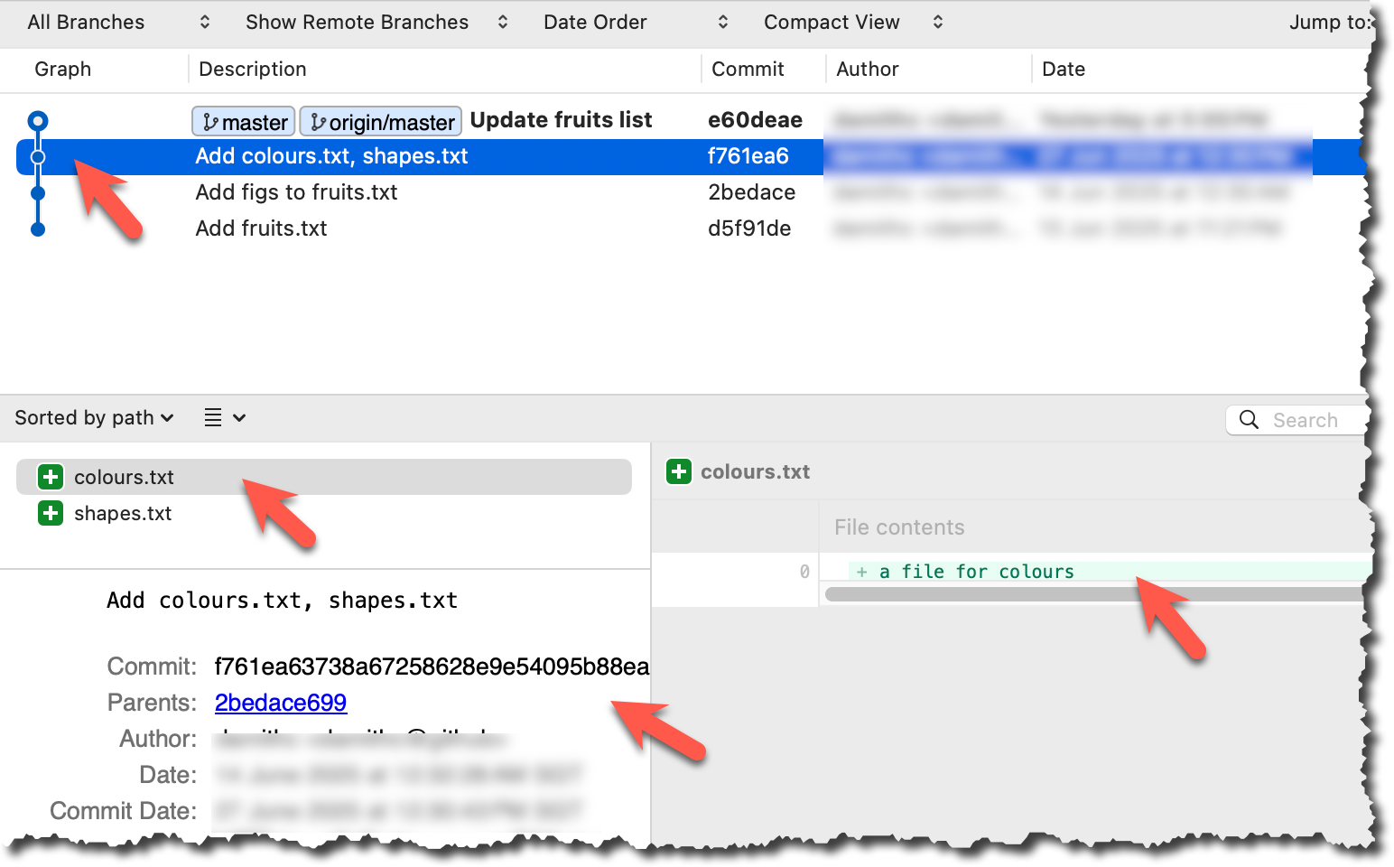
done!
PRO-TIP: Use Git Aliases to Work Faster
The Git alias feature allows you to create custom shortcuts for frequently used Git commands. This saves time and reduces typing, especially for long or complex commands. Once an alias is defined, you can use the alias just like any other Git command e.g., use git lod as an alias for git log --oneline --decorate.
To define a global git alias, you can use the git config --global alias.<alias> "command" command. e.g.,
git config --global alias.lod "log --oneline --graph --decorate"
You can also create shell-level aliases using your shell configuration (e.g., .bashrc, .zshrc) to make even shorter aliases. This lets you create shortcuts for any command, including Git commands, and even combine them with other tools. e.g., instead of the Git alias git lod, you can define a shorter shell-level alias glod.
1. Locate your .bash_profile file (likely to be in : C:\Users\<YourName>\.bash_profile -- if it doesn’t exist, create it.)
1. Locate your shell's config file e.g., .bashrc or .zshrc (likely to be in your ~ folder)
1. Locate your shell's config file e.g., .bashrc or .zshrc (likely to be in your ~ folder)
Oh-My-Zsh for Zsh terminal supports a Git plugin that adds a wide array of Git command aliases to your terminal.
2. Add aliases to that file:
alias gs='git status'
alias glod='git log --oneline --graph --decorate'
3. Apply changes by running the command source ~/.zshrc or source ~/.bash_profile or source ~/.bashrc, depending on which file you put the aliases in.
When working with many commits, it helps to tag specific commits with custom names so they’re easier to refer to later.
Git lets you tag commits with names, making them easy to reference later. This is useful when you want to mark specific commits -- such as releases or key milestones (e.g., v1.0 or v2.1). Using tags to refer to commits is much more convenient than using SHA hashes. In the diagram below, v1.0 and interim are tags.
A tag stays fixed to the commit. Unlike branch refs or HEAD, tags do not move automatically as new commits are made. As you see below, after adding a new commit, tags stay in the previous commits while master←HEAD have moved to the new commit.
Git supports two kinds of tags:
- A lightweight tag is just a ref that points directly to a commit, like a branch that doesn’t move.
- An annotated tag is a full Git object that stores a reference to a commit along with metadata such as the tagger’s name, date, and a message.
Annotated tags are generally preferred for versioning and public releases, while lightweight tags are often used for less formal purposes, such as marking a commit for your own reference.
0 Preparation: fork and clone the samplerepo-preferences. Use the cloned repo on your computer for the following steps.
1 Add a lightweight tag to the current commit as v1.0:
git tag v1.0
2 Verify the tag was added. To view tags:
git tag
v1.0
To view tags in the context of the revision graph:
git log --oneline --decorate
507bb74 (HEAD -> master, tag: v1.0, origin/master, origin/HEAD) Add donuts
de97f08 Add cake
5e6733a Add bananas
3398df7 Add food.txt
3 Use the tag to refer to the commit e.g., git show v1.0 should show the changes in the tagged commit.
4 Add an annotated tag to an earlier commit. The example below adds a tag v0.9 to the commit HEAD~2 with the message First beta release. The -a switch tells Git this is an annotated tag.
git tag -a v0.9 HEAD~2 -m "First beta release"
5 Check the new annotated tag. While both types of tags appear similarly in the revision graph, the show command on an annotated tag will show the details of the tag and the details of the commit it points to.
git show v0.9
tag v0.9
Tagger: ... <...@...>
Date:   Sun Jun ...

First beta release

commit ....999087124af... (tag: v0.9)
Author: ... <...@...>
Date:   Sat Jun ...

    Add figs to fruits.txt

diff --git a/fruits.txt b/fruits.txt
index a8a0a01..7d0a594 100644
# rest of the diff goes here
Right-click on the commit (in the graphical revision graph) you want to tag and choose Tag….
Specify the tag name e.g., v1.0 and click Add Tag.
Configure tag properties in the next dialog and press Add. For example, you can choose whether to make it a lightweight tag or an annotated tag (default).
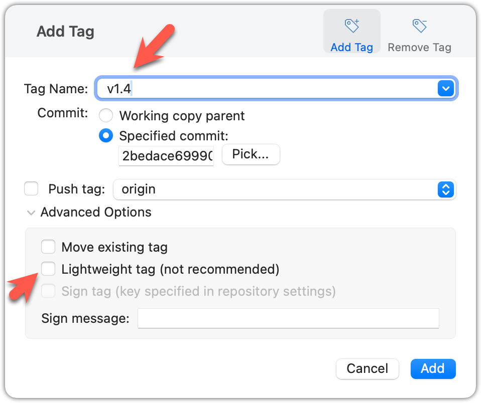
Tags will appear as labels in the revision graph, as seen below. To see the details of an annotated tag, you need to use the menu indicated in the screenshot.
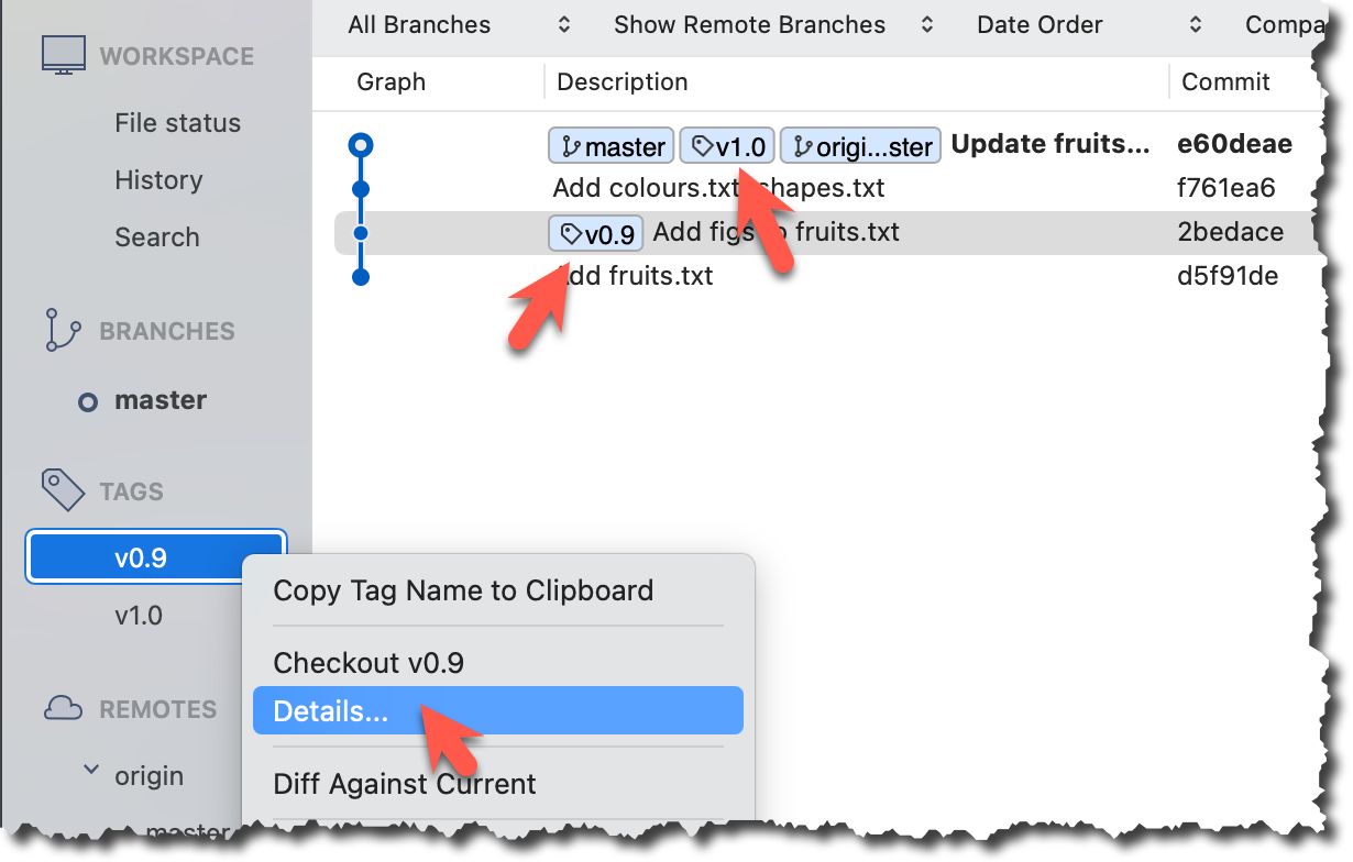
done!
If you need to change what a tag points to, you must delete the old one and create a new tag with the same name. This is because tags are designed to be fixed references to a specific commit, and there is no built-in mechanism to 'move' a tag.
Move the v1.0 tag to the commit HEAD~1, by deleting it first and creating it again at the destination commit.
Delete the previous v1.0 tag by using the -d switch. Add it again to the other commit, as before.
git tag -d v1.0
git tag v1.0 HEAD~1
The same dialog used to add a tag can be used to delete and even move a tag. Note that the 'moving' here translates to deleting and re-adding behind the scene.
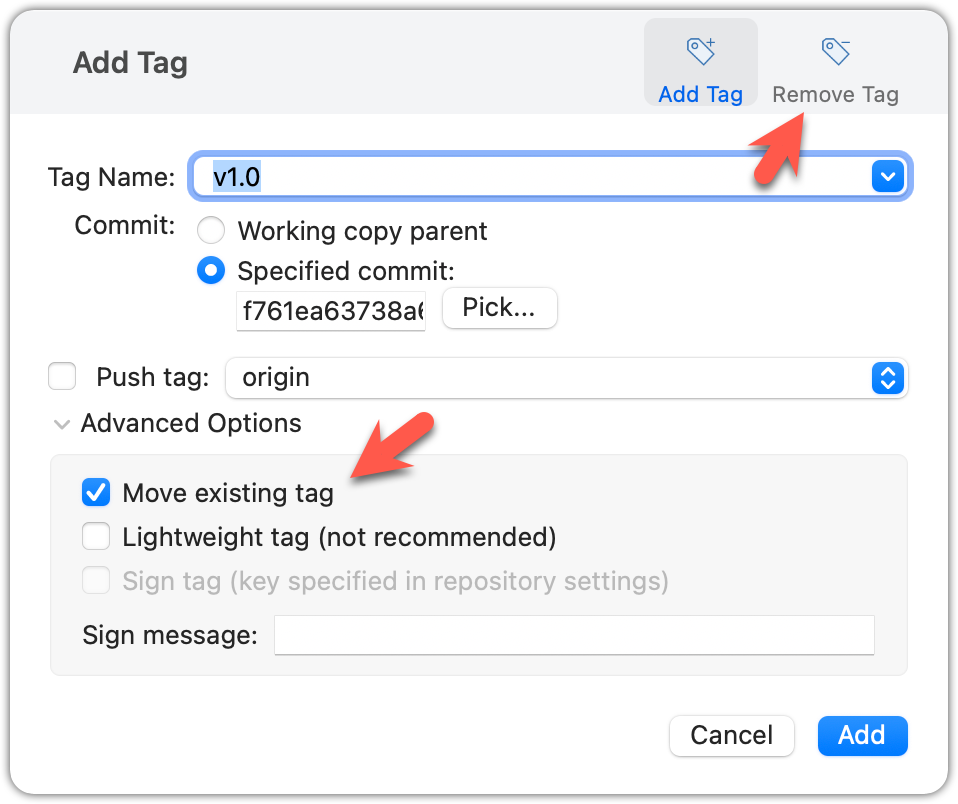
done!
Tags are different from commit messages, in purpose and in form. A commit message is a description of the commit that is part of the commit itself. A tag is a short name for a commit, which you can use to address a commit.
Pushing commits to a remote does not push tags automatically. You need to push tags specifically.
Push tags you created earlier to the remote.
You can go to your remote on GitHub link https://github.com/{USER}/{REPO}/tags (e.g., https://github.com/johndoe/samplerepo-prefrences/tags) to verify the tag is present there.
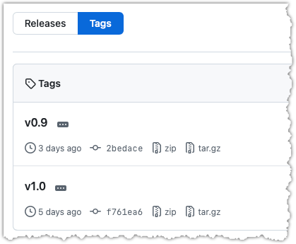
Note how GitHub assumes these tags are meant as releases, and automatically provides zip and tar.gz archives of the repo (as at that tag).
1 Push a specific tag in the local repo to the remote (e.g., v1.0) using the git push <origin> <tag-name> command.
git push origin v1.0
In addition to verifying the tag's presence via GitHub, you can also use the following command to list the tags presently in the remote.
git ls-remote --tags origin
2 Delete a tag in the remote, using the git push --delete <remote> <tag-name> command.
git push --delete origin v1.0
3 Push all tags to the remote repo, using the git push <remote> --tags command.
git push origin --tags
To push a specific tag, use the following menu:
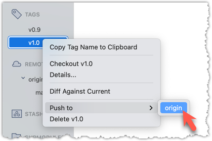
To push all tags, you can tick the Push all tags option when pushing commits:
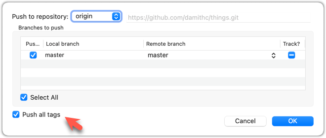
done!
Git can tell you the net effect of changes between two points of history.
Git's diff feature can show you what changed between two points in the revision history. Given below are some use cases.
Usage 1: Examining changes in the working directory
Example use case: To verify the next commit will include exactly what you intend it to include.
Preparation For this, you can use the things repo you created earlier. If you don't have it, you can clone a copy of a similar repo given here.
1 Do some changes to the working directory. Stage some (but not all) changes. For example, you can run the following commands.
echo -e "blue\nred\ngreen" >> colours.txt
git add .  # a shortcut to stage all changes
echo "no shapes added yet" >> shapes.txt
2 Examine the staged and unstaged changes.
The git diff command shows unstaged changes in the working directory (tracked files only). The output of the diff command, is a diff view (introduced in this lesson).
git diff
diff --git a/shapes.txt b/shapes.txt
index 5c2644b..949c676 100644
--- a/shapes.txt
+++ b/shapes.txt
@@ -1 +1,2 @@
a file for shapes
+no shapes added yet!
The git diff --staged command shows the staged changes (same as git diff --cached).
git diff --staged
Select the two commits: Click on one commit, and Ctrl-Click (or Cmd-Click) on the second commit. The changes between the two selected commits will appear in the other panels, as shown below:
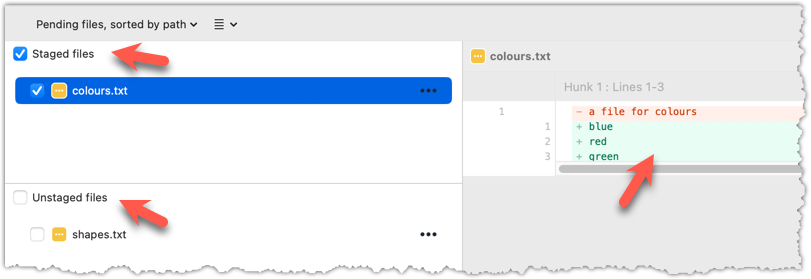
done!
Usage 2: Comparing two commits at different points of the revision graph
Example use case: Suppose you’re trying to improve the performance of a piece of software by experimenting with different code tweaks. You commit after each change (as you should). After several commits, you now want to review the overall effect of all those changes on the code.
Compare two commits in a repo (e.g., the things repo).
You can use the git diff <commit1> <commit2> command for this.
- You may use any valid way to refer to commits (e.g., SHA, tag, HEAD~n etc.).
- You may also use the
..notation to specify the commit range too e.g.,0023cdd..fcd6199,HEAD~2..HEAD
git diff v0.9 HEAD
diff --git a/colours.txt b/colours.txt
new file mode 100644
index 0000000..55c8449
--- /dev/null
+++ b/colours.txt
@@ -0,0 +1 @@
+a file for colours
# rest of the diff ...
Swap the commit order in the command and see what happens.
git diff HEAD v0.9
diff --git a/colours.txt b/colours.txt
deleted file mode 100644
index 55c8449..0000000
--- a/colours.txt
+++ /dev/null
@@ -1 +0,0 @@
-a file for colours
# rest of the diff ...
As you can see, the diff is directional i.e., dif <commit1> <commit2> shows what changes you need to do to go from the <commit1> to <commit2>. If you swap <commit1> and <commit2>, the output will change accordingly e.g., lines previously shown as 'added' will now be shown as 'deleted'.
Select the two commits: Click on one commit, and Ctrl-Click (or Cmd-Click) on the second commit. The changes between the two selected commits will appear in the other panels, as shown below:
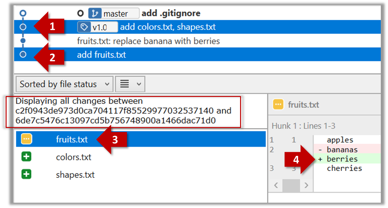
The same method can be used to compare the current state of the working directory (which might have uncommitted changes) to a point in the history.
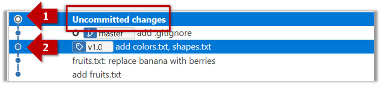
done!
Usage 3: Examining changes to a specific file
Example use case: Similar to other use cases but when you are interested in a specific file only.
Examine the changes done to a file between two different points in the version history (including the working directory).
Add the -- path/to/file to a previous diff command to narrow the output to a specific file. Some examples:
git diff -- fruits.txt               # unstaged changes to fruits.txt
git diff --staged -- src/main.java   # staged changes to src/main.java
git diff HEAD~2..HEAD -- fruits.txt  # changes to fruits.txt between commits
Sourcetree UI shows changes to one file at a time by default; just click on the file to view changes to that file. To view changes to multiple files, Ctrl-Click (or Cmd-Click) on multiple files to select them.
done!
Another useful feature of revision control is to be able to view the working directory as it was at a specific point in history, by checking out a commit created at that point.
Suppose you added a new feature to a software product, and while testing it, you noticed that another feature added two commits ago doesn’t handle a certain edge case correctly. Now you’re wondering: did the new feature break the old one, or was it already broken? Can you go back to the moment you committed the old feature and test it in isolation, and come back to the present after you found the answer? With Git, you can.
To view the working directory at a specific point in history, you can check out a commit created at that point.
When you check out a commit, Git:
- Updates your working directory to match the snapshot in that commit, overwriting current files as needed.
- Moves the
HEADref to that commit, marking it as the current state you’re viewing.
→
[check out commit C2...]
Checking out a specific commit puts you in a "detached HEAD" state: i.e., the HEAD no longer points to a branch, but directly to a commit (see the above diagram for an example). This isn't a problem by itself, but any commits you make in this state can be lost, unless certain follow-up actions are taken. It is perfectly fine to be in a detached state if you are only examining the state of the working directory at that commit.
To get out of a "detached HEAD" state, you can simply check out a branch, which "re-attaches" HEAD to the branch you checked out.
→
[check out master...]
Checkout a few commits in a local repo (e.g., the things repo), while examining the working directory to verify that it matches the state when you created the corresponding commit:
1 Examine the revision tree, to get your bearing first.
git log --oneline --decorate
Reminder: You can use aliases to reduce typing Git commands.
e60deae (HEAD -> master, origin/master) Update fruits list
f761ea6 (tag: v1.0) Add colours.txt, shapes.txt
2bedace (tag: v0.9) Add figs to fruits.txt
d5f91de Add fruits.txt
2 Use the checkout <commit-identifier> command to check out a commit other than the one currently pointed by HEAD. You can use any of the following methods:
git checkout v1.0: checks out the commit taggedv1.0git checkout 0023cdd: checks out the commit with the hash0023cddgit checkout HEAD~2: checks out the commit 2 commits behind the most recent commit.
git checkout HEAD~2
Note: switching to 'HEAD~2'.

You are in 'detached HEAD' state.
# rest of the warning about the detached head ...

HEAD is now at 2bedace Add figs to fruits.txt
3 Verify HEAD and the working directory have updated as expected.
HEADshould now be pointing at the target commit- The working directory should match the state it was in at that commit (e.g., files added after that commit -- such as
shapes.txtshould not be in the folder).
git log --one-line --decorate
2bedace (HEAD, tag: v0.9) Add figs to fruits.txt
d5f91de Add fruits.txt
HEAD is indeed pointing at the target commit.
But note how the output does not show commits you added after the checked-out commit.
The --all switch tells git log to show commits from all refs, not just those reachable from the current HEAD. This includes commits from other branches, tags, and remotes.
git log --one-line --decorate --all
e60deae (origin/master, master) Update fruits list
f761ea6 (tag: v1.0) Add colours.txt, shapes.txt
2bedace (HEAD, tag: v0.9) Add figs to fruits.txt
d5f91de Add fruits.txt
4 Go back to the latest commit by checking out the master branch again.
git checkout master
In the revision graph, double-click the commit you want to check out, or right-click on that commit and choose Checkout....
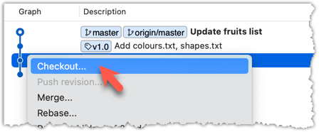
Click OK to the warning about ‘detached HEAD’ (similar to below).
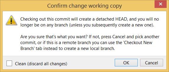
The specified commit is now loaded onto the working folder, as indicated by the HEAD label.
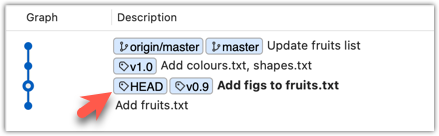
To go back to the latest commit on the master branch, double-click the master branch.
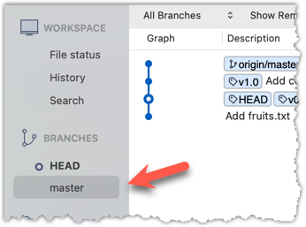
If you check out a commit that comes before the commit in which you added a certain file (e.g., temp.txt) to the .gitignore file, and if the .gitignore file is version controlled as well, Git will now show it under ‘unstaged modifications’ because at Git hasn’t been told to ignore that file yet.
done!
If there are uncommitted changes in the working directory, Git proceeds with a checkout only if it can preserve those changes.
- Example 1: There is a new file in the working directory that is not committed yet.
→ Git will proceed with the checkout and will keep the uncommitted file as well. - Example 2: There is an uncommitted change to a file that conflicts with the version of that file in the commit you wish to check out.
→ Git will abort the checkout, and the repo will remain in the current commit.
The Git stash feature temporarily set aside uncommitted changes you’ve made (in your working directory and staging area), without committing them. This is useful when you’re in the middle of some work, but need to switch to another state (e.g., checkout a previous commit), and your current changes are not yet ready to be committed or discarded. You can later reapply the stashed changes when you’re ready to resume that work.
Git can also reset the revision history to a specific point so that you can start over from that point.
Suppose you realise your last few commits have gone in the wrong direction, and you want to go back to an earlier commit and continue from there — as if the “bad” commits never happened. Git’s reset feature can help you do that.
Git reset moves the tip of the current branch to a specific commit, optionally adjusting your staged and unstaged changes to match. This effectively rewrites the branch's history by discarding any commits that came after that point.
Resetting is different from the checkout feature:
- Reset: Lets you start over from a past state. It rewrites history by moving the branch ref to a new location.
- Checkout: Lets you explore a past state without rewriting history. It just moves the
HEADref.
→
[reset to C2...]
master branch!There are three types of resets: soft, mixed, hard. All three moves the branch pointer to a new commit but they vary based on what happens to the staging area and the working directory.
- soft reset: Moves the cumulative changes from the discarded commits in to the staging area, waiting to be committed again. Any staged and unstaged changes that existed before the reset will remain untouched.
- mixed reset: Cumulative changes from the discarded commits, and any existing staged changes, are moved into the working directory.
- hard reset: All staged and unstaged changes are discarded. Both the working directory and the staging area are aligned with the target commit (as if no changes were done after that commit).
1 First, set the stage as follows (e.g., in the things repo):
i) Add four commits that are supposedly 'bad' commits.
ii) Do a 'bad' change to one file and stage it.
iii) Do a 'bad' change to another file, but don't stage it.
The following commands can be used to add commits B1-B4:
echo "bad colour" >> colours.txt
git commit -am "Incorrectly update colours.txt"

echo "bad shape" >> shapes.txt
git commit -am "Incorrectly update shapes.txt"

echo "bad fruit" >> fruits.txt
git commit -am "Incorrectly update fruits.txt"

echo "bad line" >> incorrect.txt
git add incorrect.txt
git commit -m "Add incorrect.txt"

echo "another bad colour" >> colours.txt
git add colours.txt

echo "another bad shape" >> shapes.txt
Now we have some 'bad' commits and some 'bad' changes in both the staging area and the working directory. Let's use the reset feature to get rid of all of them, but do it in three steps so that you can learn all three types of resets.
2 Do a soft reset to B2 (i.e., discard last two commits). Verify,
- the
masterbranch is now pointing atB2, and, - the changes that were in the discarded commits (i.e.,
B3andB4) are now in the staging area.
Use the git reset --soft <commit> command to do a soft reset.
git reset --soft HEAD~2
You can run the following commands to verify the current status of the repo is as expected.
git status                    # check overall status
git log --oneline --decorate  # check the branch tip
git diff                      # check unstaged changes
git diff --staged             # check staged changes
Right-click on the commit that you want to reset to, and choose Reset <branch-name> to this commit option.
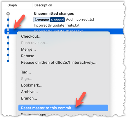
In the next dialog, choose Soft - keep all local changes.
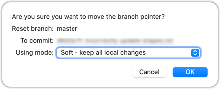
3 Do a mixed reset to commit B1. Verify,
- the
masterbranch is now pointing atB1. - the staging area is empty.
- the accumulated changes from all three discarded commits (including those from the previous soft reset) are now appearing as unstaged changes in the working directory.
Note howincorrect.txtappears as an 'untracked' file -- this is because unstaging a change of type 'add file' results in an untracked file.
Use the git --mixed reset <commit> command to do a mixed reset. The --mixed flag is the default, and can be omitted.
git reset HEAD~1
Verify the repo status, as before.
Similar to the previous reset, but choose the Mixed - keep working copy but reset index option in the reset dialog.
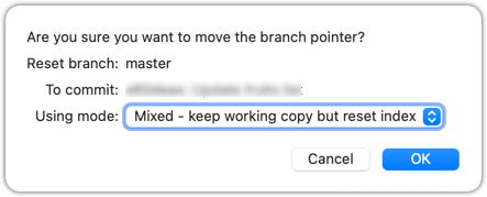
4 Do a hard reset to commit C4. Verify,
- the
masterbranch is now pointing atC4i.e., all 'bad' commits are gone. - the staging area is empty.
- there are no unstaged changes (except for the untracked files
incorrect.txt-- Git leaves untracked files alone, as untracked files are not meant to be under Git's control).
Use the git --hard reset <commit> command.
git reset --hard HEAD~1
Verify the repo status, as before.
Similar to the previous reset, but choose the Hard - discard all working copy changes option.
done!
Rewriting history can cause your local repo to diverge from its remote counterpart. For example, if you discard earlier commits and create new ones in their place, and you’ve already pushed the original commits to a remote repository, your local branch history will no longer match the corresponding remote branch. Git refers to this as a diverged history.
To protect the integrity of the remote, Git will reject attempts to push a diverged branch using a normal push. If you want to overwrite the remote history with your local version, you must perform a force push.
Preparation Choose a local-remote repo pair under your control e.g., the things repo from Tour 2: Backing up a Repo on the Cloud.
1 Rewrite the last commit: Reset the current branch back by one commit, and add a new commit.
For example, you can use the following commands.
git reset --hard HEAD~1
echo "water" >> drinks.txt
git add .
git commit -m "Add drinks.txt"
2 Observe how the local branch is diverged.
git log --oneline --graph --all
* fc1d04e (HEAD -> master) Add drinks.txt
| * e60deae (upstream/master, origin/master) Update fruits list
|/
* f761ea6 (tag: v1.0) Add colours.txt, shapes.txt
* 2bedace (tag: v0.9) Add figs to fruits.txt
* d5f91de Add fruits.txt
3 Attempt to push to the remote. Observe Git rejects the push.
git push origin master
To https://github.com/.../things.git
 ! [rejected]        master -> master (non-fast-forward)
error: failed to push some refs to 'https://github.com/.../things.git'
hint: Updates were rejected because the tip of your current branch is behind
hint: its remote counterpart. If you want to integrate the remote changes,
hint: ...
4 Do a force-push.
You can use the --force (or -f) flag to force push.
git push -f origin master
A safer alternative to --force is --force-with-lease which overwrites the remote branch only if it hasn’t changed since you last fetched it (i.e., only if remote doesn't have recent changes that you are unaware of):
git push -force-with-lease origin master
done!
Git can add a new commit to reverse the changes done in a specific past commit, called reverting a commit.
When a past commit introduced a bug or an unwanted change, but you do not want to modify that commit — because rewriting history can cause problems if others have already based work on it — you can instead revert that commit.
Reverting creates a new commit that cancels out the changes of the earlier one i.e., Git computes the opposite of the changes introduced by that commit — essentially a reverse diff — and applies it as a new commit on top of the current branch. This way, the problematic changes are reversed while preserving the full history, including the "bad" commit and the "fix".
→
[revert C2]
C2Preparation Run the following commands to create a repo with a few commits:
mkdir pioneers
cd pioneers
git init

echo "hacked the matrix" >> neo.txt
git add .
git commit -m "Add Neo"

echo "father of theoretical computing" >> alan-turing.txt
git add .
git commit -m "Add Turing"

echo "created COBOL, compiler pioneer" >> grace-hopper.txt
git add .
git commit -m "Add Hopper"
1 Revert the commit Add Neo.
You can use the git revert <commit> command to revert a commit. In this case, we want to revert the commit that is two commits behind the HEAD.
git revert HEAD~2
What happens next:
- Git prepares a new commit which reverses the target commit
- Git opens your default text editor containing a proposed commit message. You can edit it, or accept the proposed text.
- Once you close the editor, Git will create the new commit.
In the revision graph, right-click on the commit you want to revert, and choose Reverse commit...
done!
A revert can result in a conflict, if the new changes done to reverse the previous commit conflict with the changes done in other more recent commits. Then, you need to resolve the conflict before the revert operation can proceed. Conflict resolution is covered in a later topic.
To create well-crafted commits, you need to know how to control which precise changes go into a commit.
Crafting a commit involves two aspects:
- What changes to include in it: deciding what changes belong together in a single commit — this is about commit granularity, ensuring each commit represents a meaningful, self-contained change.
- How to include those changes: carefully staging just those changes — this is about using Git’s tools to precisely control what ends up in the commit.
SIDEBAR: Guidelines on what to include in a commit
A good commit represents a single, logical unit of change — something that can be described clearly in one sentence. For example, fixing a specific bug, adding a specific feature, or refactoring a specific function. If each commit tells a clear story about why the change was made and what it achieves, your repository history becomes a valuable narrative of the project’s development. Here are some (non-exhaustive) guidelines:
- No more than one change per commit: Avoid lumping unrelated changes into one commit, as this makes the history harder to understand, review, or revert (if each commit contains one standalone change, to reverse that change can be done by deleting or reverting that specific commit entirely, without affecting any other changes).
- Make the commit standalone: Don’t split a single logical change across multiple commits unnecessarily, as this can clutter the history and make it harder to follow the evolution of an idea or feature.
- Small enough to review easily, but large enough to stand on its own: For example, fixing the same typo in five files can be one commit — splitting it into five separate commits is excessive. Conversely, implementing a big feature may be too much for one commit — instead, break it down into a series of commits, each containing a meaningful yet standalone step towards the final goal.
Git can let you choose not just which files, but which specific changes within those files, to include in a commit. Most Git tools — including the command line and many GUIs — let you interactively select which "hunks" or even individual lines of a file to stage. This allows you to separate unrelated changes and avoid committing unnecessary edits. If you make multiple changes in the same file, you can selectively stage only the parts that belong to the current logical change.
This level of control is particularly useful when:
- You noticed and fixed a small, unrelated issue while working on something else.
- You experimented with multiple approaches in the same file and now want to commit only the final, clean solution.
- You want your commit history to clearly separate concerns, even when the edits touch the same files.
You can use any repo for this.
1 Do several changes to some tracked files. Change multiple files. Also change multiple locations in the same file.
2 Stage some changes in some files while keeping other changes in the same files unstaged.
As you know, you can use git add <filename> to stage changes to an entire file.
To select which hunks to stage, you can use the git add -p command instead (-p stands for 'by patch'):
git add -p
This command will take you to an interactive mode in which you can go through each hunk and decide if you want to stage it. The video below has contains a demonstration of how this feature works:
To stage a hunk, you can click the Stage button above the hunk in question:
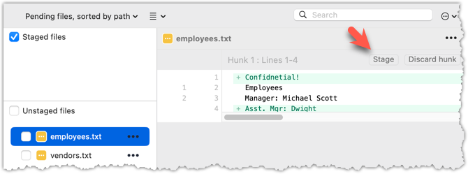
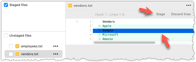 Unstaging can be done similarly:
Most git operations can be done faster through the CLI than equivalent Git GUI clients, once you are familiar enough with the CLI commands.
However, selective staging is one exception where a good GUI can do better than the CLI, if you need to do many fine-grained staging operations (e.g., frequently staging only parts of hunks).
done!
Detailed and well-written commit messages can increase the value of Git revision history.
Every commit you make in Git also includes a commit message that explains the change. While one-line messages are fine for small or obvious changes, as your revision history grows, good commit messages become an important source of information — for example, to understand the rationale behind a specific change made in the past.
A commit message is meant to explain the intent behind the changes, not just what was changed. The code (or diff) already shows what changed. Well-written commit messages make collaboration, code reviews, debugging, and future maintenance easier by helping you and others quickly understand the project’s history without digging into the code of every commit.
A complete commit message can include a short summary line (the subject) followed by a more detailed body if needed. The subject line should be a concise description of the change, while the body can elaborate on the context, rationale, side effects, or other details if the change is more complex.
Here is an example commit message:
Find command: make matching case-insensitive

Find command is case-sensitive.

A case-insensitive find is more user-friendly because users cannot be
expected to remember the exact case of the keywords.

Let's,
* update the search algorithm to use case-insensitive matching
* add a script to migrate stress tests to the new format
Following a style guide makes your commit messages more consistent and fit-for-purpose. Many teams adopt established guidelines. These style guides typically contain common conventions that Git users follow when writing commit messages. For example:
- Keep the subject line (the first line) under 50–72 characters.
- Write the subject in the imperative mood (e.g.,
Fix typo in READMErather thanFixed typoorFixes typo). - Leave a blank line between the subject and the body, if you include a body.
- Wrap the body at around 72 characters per line for readability.
When the revision history get 'messy', Git has a way to 'tidy up' the recent commits.
Git has a powerful tool called interactive rebasing which lets you review and reorganise your recent commits. With it, you can reword commit messages, change their order, delete commits, combine several commits into one (squash), or split a commit into smaller pieces. This feature is useful for tidying up a commit history that has become messy — for example, when some commits are out of order, poorly described, or include changes that would be clearer if split up or combined.
Run the following commands to create a sample repo that we'll be using for this hands-on practical:
mkdir samplerepo-sitcom
cd samplerepo-sitcom
git init

echo "Aspiring actress" >> Penny.txt
git add .
git commit -m "C1: Add Penny.txt"

echo "Scientist" >> Sheldon.txt
git add .
git commit -m "C3: Add Sheldon.txt"

echo "Comic book store owner" >> Stuart.txt
git add .
git commit -m "C2: Add Stuart.txt"

echo "Engineer" >> Stuart.txt
git commit -am "X: Incorrectly update Stuart.txt"

echo "Engineer" >> Howard.txt
git add .
git commit -m "C4: Adddd Howard.txt"
Here are the commits that should be in the created repo, and how each commit needs to be 'tidied up'.
C4: Adddd Howard.txt-- Fix typo in the commit messageAdddd→Add.X: Incorrectly update Stuart.txt-- Drop this commit.C2: Add Stuart.txt-- Swap this commit with the one below.C3: Add Sheldon.txt-- Swap this commit with the one above.C1: Add Penny.txt-- No change required.
To start the interactive rebase, use the git rebase -i <start-commit> command. -i stands for 'interactive'. In this case, we want to modify the last four commits (hence, HEAD~4).
git rebase -i HEAD~4
pick 97a8c4a C3: Add Sheldon.txt
pick 60bd28d C2: Add Stuart.txt
pick 8b9a36f X: Incorrectly update Stuart.txt
pick 8ab6941 C4: Adddd Howard.txt

# Rebase ee04afe..8ab6941 onto ee04afe (4 commands)
#
# Commands:
# p, pick <commit> = use commit
# r, reword <commit> = use commit, but edit the commit message
# e, edit <commit> = use commit, but stop for amending
# s, squash <commit> = use commit, but meld into previous commit
# f, fixup [-C | -c] <commit> = like "squash" but keep only the previous
#                    commit's log message, unless -C is used, in which case
#                    keep only this commit's message; -c is same as -C but
#                    opens the editor
# x, exec <command> = run command (the rest of the line) using shell
# b, break = stop here (continue rebase later with 'git rebase --continue')
# d, drop <commit> = remove commit
# l, label <label> = label current HEAD with a name
# t, reset <label> = reset HEAD to a label
# m, merge [-C <commit> | -c <commit>] <label> [# <oneline>]
#         create a merge commit using the original merge commit's
#         message (or the oneline, if no original merge commit was
#         specified); use -c <commit> to reword the commit message
# u, update-ref <ref> = track a placeholder for the <ref> to be updated
#                       to this position in the new commits. The <ref> is
#                       updated at the end of the rebase
#
# These lines can be re-ordered; they are executed from top to bottom.
#
# If you remove a line here THAT COMMIT WILL BE LOST.
#
# However, if you remove everything, the rebase will be aborted.
#
The command will take you to the text editor, which will present you with a wall of text similar to the above. It has two parts:
- At the top, the list of commits and the action to take on each, oldest commit first, with the action
pickindicated by default (pickmeans 'use this commit in the result') for each. - At the bottom, instructions on how to edit those lines.
Edit the commit list to specify the rebase actions, as follows:
pick 60bd28d C2: Add Stuart.txt
pick 97a8c4a C3: Add Sheldon.txt
drop 8b9a36f X: Incorrectly update Stuart.txt
reword 8ab6941 C4: Addddd Howard.txt
Once you exit the text editor, Git will perform the rebase based on the actions you specified, from top to bottom.
At some steps, Git will pause the rebase and ask for your inputs. In this case, it will ask you to specify the new commit message when it is processing the following line.
reword 8ab6941 C4: Addddd Howard.txt
To go to the interactive rebase mode, right-click the parent commit of the earliest commit you want to reorganise (in this case, it is C1: Add Penny.txt) and choose Rebase children of <SHA> interactively...
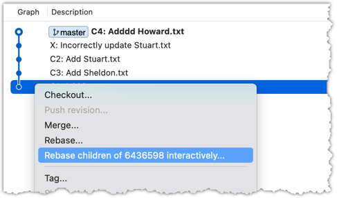
To indicate what action you want to perform on each commit, select the commit in the list and click on the button for the action you want to do on it:
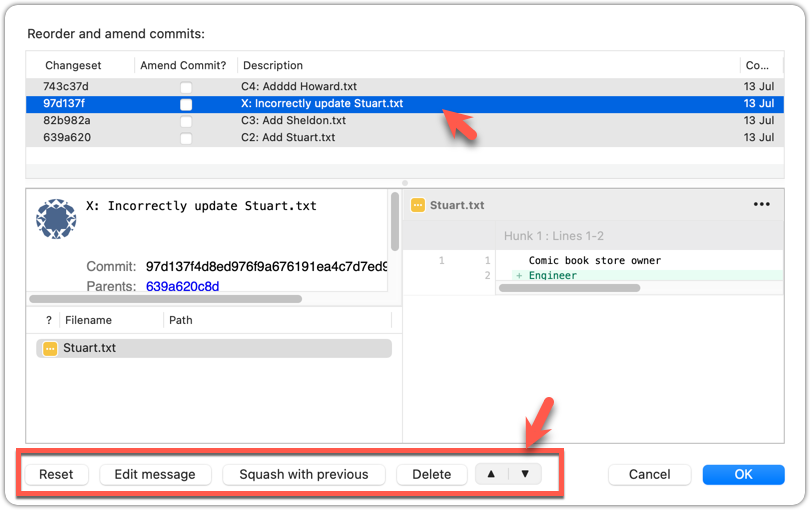
To execute the rebase, after indicating the action for all commits (the dialog will look like the below), click OK.
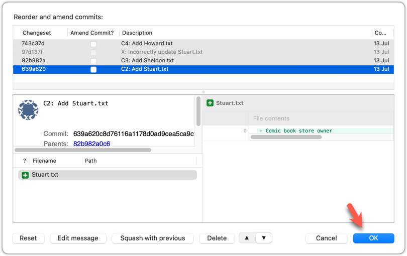
The final result should be something like the below, 'tidied up' exactly as we wanted:
* 727d877 C4: Add Howard.txt
* 764fc29 C3: Add Sheldon.txt
* 08a965a C2: Add Stuart.txt
* 6436598 C1: Add Penny.txt
done!
Rebasing rewrites history. It is not recommended to rebase commits you have already shared with others.
To work in parallel timelines, you can use Git branches.
Git branches let you develop multiple versions of your work in parallel — effectively creating diverged timelines of your repository’s history. For example, one team member can create a new branch to experiment with a change, while the rest of the team continues working on another branch. Branches can have meaningful names, such as master, release, or draft.
A Git branch is simply a ref (a named label) that points to a commit and automatically moves forward as you add new commits to that branch. As you’ve seen before, the HEAD ref indicates which branch you’re currently working on, by pointing to corresponding branch ref.
When you add a commit, it goes into the branch you are currently on, and the branch ref (together with the HEAD ref) moves to the new commit.
Git creates a branch named master by default (Git can be configured to use a different name e.g., main).
Given below is an illustration of how branch refs move as branches evolve. Refer to the text below it for explanations of each stage.
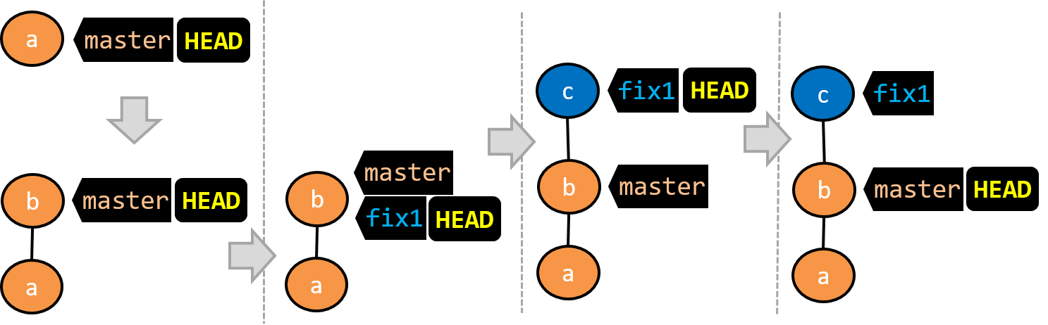
- There is only one branch (i.e.,
master) and there is only one commit on it. TheHEADref is pointing to themasterbranch (as we are currently on that branch). - A new commit has been added. The
masterand theHEADrefs have moved to the new commit. - A new branch
fix1has been added. The repo has switched to the new branch too (hence, theHEADref is attached to thefix1branch). - A new commit (
c) has been added. The current branch reffix1moves to the new commit, together with theHEADref. - The repo has switched back to the
masterbranch. Hence, theHEADhas moved back tomasterbranch's .
At this point, the repo's working directory reflects the code at commitb(notc).
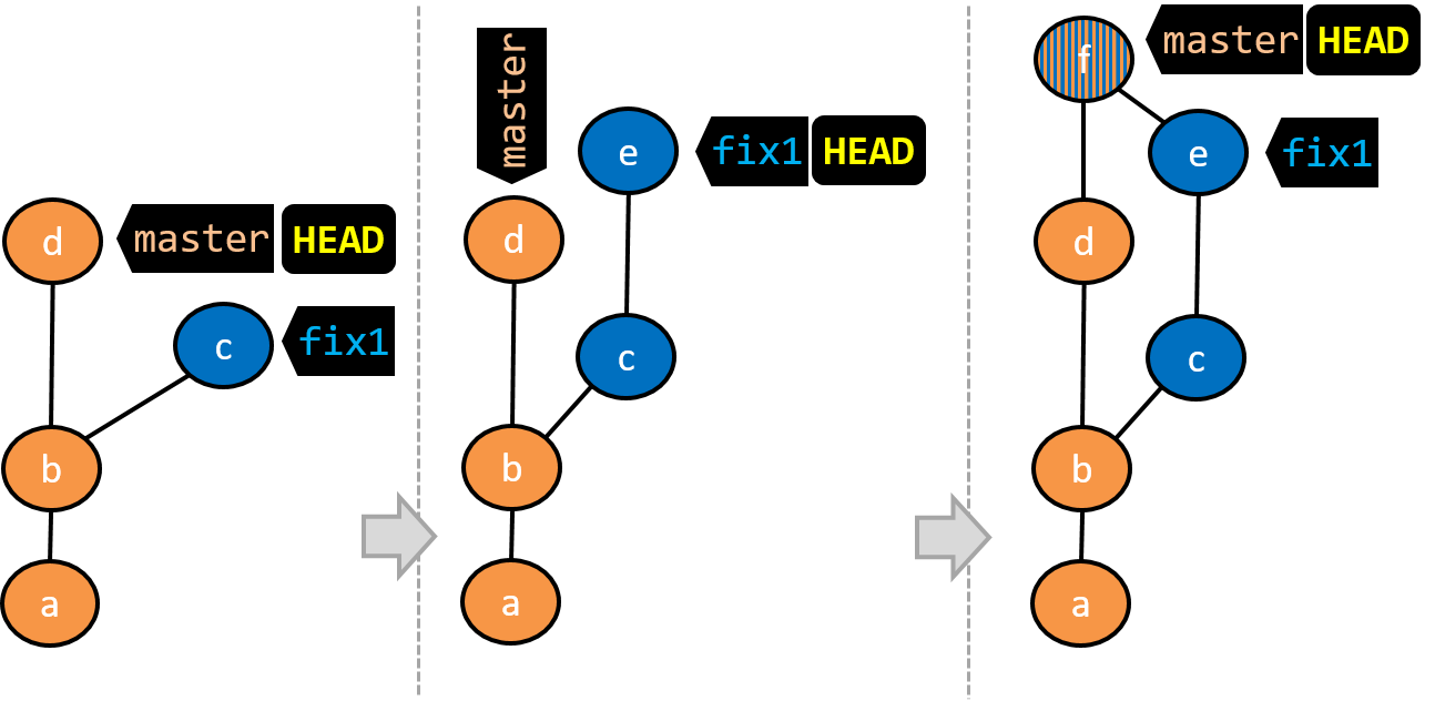
- A new commit (
d) has been added. Themasterand theHEADrefs have moved to that commit. - The repo has switched back to the
fix1branch and added a new commit (e) to it.
Note that appearance of the revision graph (colors, positioning, orientation etc.) varies based on the Git client you use, and might not match the exact diagrams given above.
1 Fork the samplerepo-things repo, and clone it onto your computer.
2 Observe that you are in the branch called master.
$ git status
on branch master
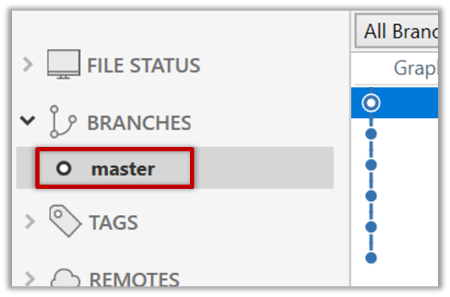
3 Start a branch named feature1 and switch to the new branch.
You can use the branch command to create a new branch and the checkout command to switch to a specific branch.
$ git branch feature1
$ git checkout feature1
One-step shortcut to create a branch and switch to it at the same time:
$ git checkout –b feature1
The new switch command
Git recently introduced a switch command that you can use instead of the checkout command given above.
To create a new branch and switch to it:
$ git branch feature1
$ git switch feature1
One-step shortcut (by using -c or --create switch):
$ git switch –c feature1
Click on the Branch button on the main menu. In the next dialog, enter the branch name and click Create Branch.
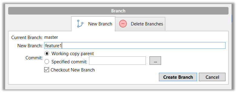
Note how the feature1 is indicated as the current branch (reason: Sourcetree automatically switches to the new branch when you create a new branch, if the Checkout New Branch was selected in the previous dialog).
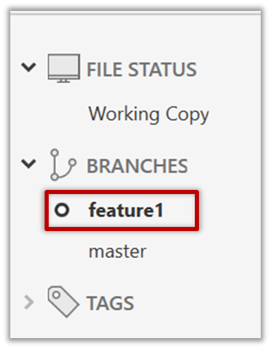
4 Create some commits in the new branch. Just commit as per normal. Commits you add while on a certain branch will become part of that branch.
Note how the master ref and the HEAD ref moves to the new commit.
As before, you can use the git log --one-line --decorate command for this.
At times, the
HEADref of the local repo is represented as in Sourcetree, as illustrated in the screenshot below .
.The
HEADref is not shown in the UI if it is already pointing at the active branch.
5 Switch to the master branch. Note how the changes you did in the feature1 branch are no longer in the working directory.
$ git switch master
Double-click the master branch.
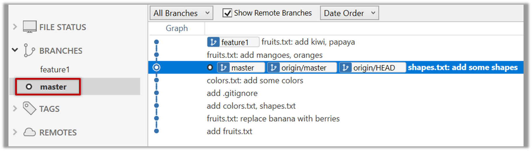
Revisiting master vs origin/master
In the screenshot above, you see a master ref and a origin/master ref for the same commit. The former identifies the of the local master branch while the latter identifies the tip of the master branch at the remote repo named origin. The fact that both refs point to the same commit means the local master branch and its remote counterpart are with each other.
Similarly, origin/HEAD ref appearing against the same commit indicates that of the remote repo is pointing to this commit as well.
6 Add a commit to the master branch. Let’s imagine it’s a bug fix.
To keep things simple for the time being, this commit should not involve the same content that you changed in the feature1 branch. To be on the safe side, you can change an entirely different file in this commit.
gitGraph BT:
    %%{init: { 'theme': 'default', 'gitGraph': {'mainBranchName': 'master'}} }%%
    commit id: "m1"
    commit id: "m2"
    branch feature1
    commit id: "f1"
    commit id: "[feature] f2"
    checkout master
    commit id: "[HEAD → master] m3"
    checkout feature1
7 Switch between the two branches and see how the working directory changes accordingly. That is, now you have two parallel timelines that you can freely switch between.
done!
You can also start a branch from an earlier commit, instead of the latest commit in the current branch. For that, simply check out the commit you wish to start from.
In the samplerepo-things repo that you used above, let's create a new branch that starts from the same commit the feature1 branch started from. Let's pretend this branch will contain an alternative version of the content we added in the feature1 branch.
gitGraph BT:
    %%{init: { 'theme': 'default', 'gitGraph': {'mainBranchName': 'master'}} }%%
    commit id: "m1"
    commit id: "m2"
    branch feature1
    branch feature1-alt
    checkout feature1
    commit id: "f1"
    commit id: "[feature1] f2"
    checkout master
    commit id: "[HEAD → master] m3"
    checkout feature1-alt
    commit id: "[HEAD → feature1-alt] a1"
Avoid this rookie mistake!
Always remember to switch back to the master branch before creating a new branch. If not, your new branch will be created on top of the current branch.
- Switch to the
masterbranch. - Checkout the commit that is at which the
feature1branch diverged from themasterbranch (e.g.git checkout HEAD~1). This will create a detachedHEAD. - Create a new branch called
feature1-alt. TheHEADwill now point to this new branch (i.e., no longer 'detached'). - Add a commit on the new branch.
done!
Most work done in branches eventually gets merged together.
Merging combines the changes from one branch into another, bringing their diverged timelines back together.
When you merge, Git looks at the two branches and figures out how their histories have diverged since their merge base (i.e., the most recent common ancestor commit of two branches). It then applies the changes from the other branch onto your current branch, creating a new commit. The new commit created when merging is called a merge commit — it records the result of combining both sets of changes.
Given below is an illustration of how such a merge looks like in the revision graph:
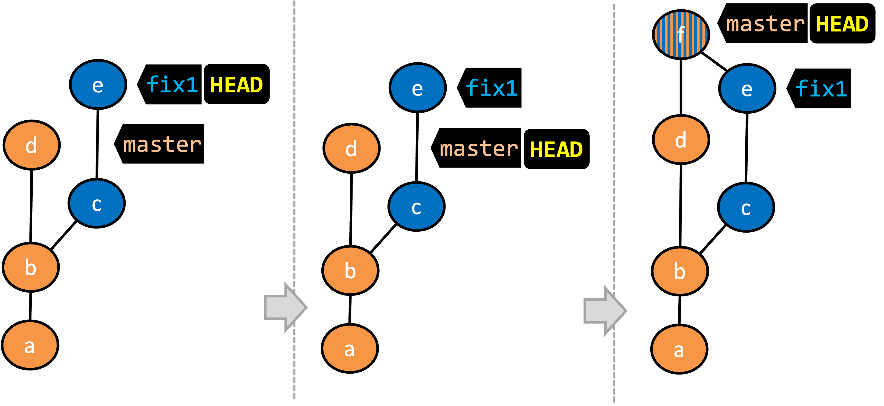
- We are on the
fix1branch (as indicated byHEAD). - We have switched to the
masterbranch (thus,HEADis now pointing tomasterref). - The
fix1branch has been merged into themasterbranch, creating a merge commitf. The repo is still on themasterbranch.
A merge commit has two parent commits e.g., in the above example, the merge commit f has both d and e as parent commits. The parent commit on the receiving branch is considered the first parent and the other is considered the second parent e.g., in the example above, fix1 branch is being merged into the master branch (i.e., the receiving branch) -- accordingly, d is the first parent and e is the second parent.
In this hands-on practical, we continue with the samplerepo-things repo from earlier, which should look like the following. Note that we are ignoring the feature1-alt branch, for simplicity.
gitGraph BT:
    %%{init: { 'theme': 'default', 'gitGraph': {'mainBranchName': 'master'}} }%%
    commit id: "m1"
    commit id: "m2"
    branch feature1
    commit id: "f1"
    commit id: "[feature] f2"
    checkout master
    commit id: "[HEAD → master] m3"
    checkout feature1
1 Switch back to the feature1 branch.
gitGraph BT:
    %%{init: { 'theme': 'default', 'gitGraph': {'mainBranchName': 'master'}} }%%
    commit id: "m1"
    commit id: "m2"
    branch feature1
    commit id: "f1"
    commit id: "[HEAD → feature1] f2"
    checkout master
    commit id: "[master] m3"
    checkout feature1
2 Merge the master branch to the feature1 branch, giving an end-result like the following. Also note how Git has created a merge commit (shown as mc1 in the diagram below).
gitGraph BT:
    %%{init: { 'theme': 'default', 'gitGraph': {'mainBranchName': 'master'}} }%%
    commit id: "m1"
    commit id: "m2"
    branch feature1
    commit id: "f1"
    commit id: "f2"
    checkout master
    commit id: "[master] m3"
    checkout feature1
    merge master id: "[HEAD → feature1] mc1"
$ git merge master
Right-click on the master branch and choose merge master into the current branch. Click OK in the next dialog.
The revision graph should look like this now (colours and line alignment might vary but the graph structure should be the same):
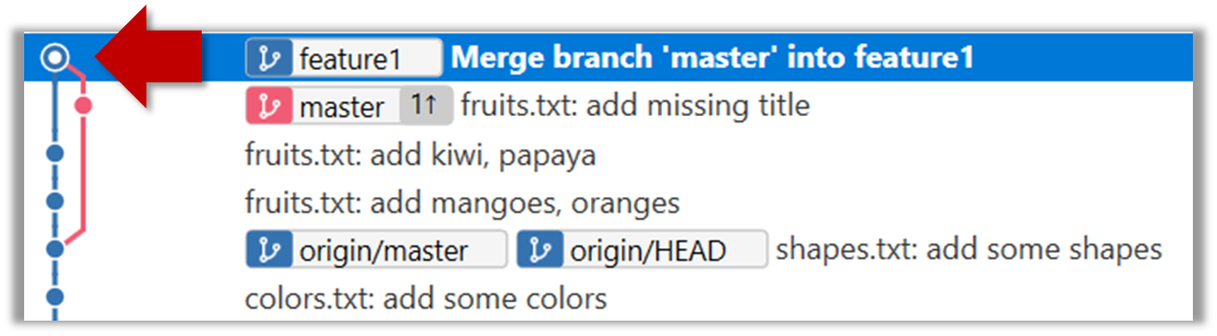
Observe how the changes you did in the master branch (i.e., the imaginary bug fix in m3) is now available even when you are in the feature1 branch.
Furthermore, observe (e.g., git show HEAD) how the merge commit contains the sum of changes done in commits m3, f1, and f2.
3 Add another commit to the feature1 branch.
Switch to the master branch and add one more commit.
gitGraph BT:
    %%{init: { 'theme': 'default', 'gitGraph': {'mainBranchName': 'master'}} }%%
    commit id: "m1"
    commit id: "m2"
    branch feature1
    commit id: "f1"
    commit id: "f2"
    checkout master
    commit id: "m3"
    checkout feature1
    merge master id: "mc1"
    commit id: "[feature1] f3"
    checkout master
    commit id: "[HEAD → master] m4"
4 Merge feature1 to the master branch, giving and end-result like this:
gitGraph BT:
    %%{init: { 'theme': 'default', 'gitGraph': {'mainBranchName': 'master'}} }%%
    commit id: "m1"
    commit id: "m2"
    branch feature1
    commit id: "f1"
    commit id: "f2"
    checkout master
    commit id: "m3"
    checkout feature1
    merge master id: "mc1"
    commit id: "[feature1] f3"
    checkout master
    commit id: "m4"
    merge feature1 id: "[HEAD → master] mc2"
git merge feature1
Right-click on the feature1 branch and choose Merge.... The resulting revision graph should look like this:
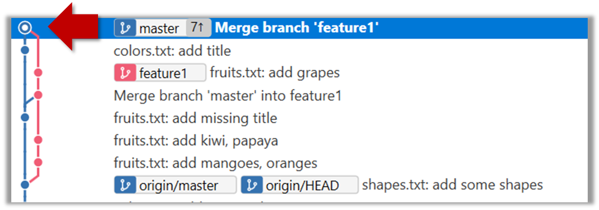
Now, any changes you did in feature1 branch are available in the master branch.
done!
When the branch you're merging into hasn't diverged — meaning it hasn't had any new commits since the merge base — Git simply moves the branch pointer forward to include all the new commits, keeping the history clean and linear. This is called a fast-forward merge because Git simply "fast-forwards" the branch pointer to the tip of the other branch. The result looks as if all the changes had been made directly on one branch, without any branching at all.
gitGraph BT:
    %%{init: { 'theme': 'default', 'gitGraph': {'mainBranchName': 'master'}} }%%
    commit id: "m1"
    commit id: "[HEAD → master] m2"
    branch bug-fix
    commit id: "b1"
    commit id: "[bug-fix] b2"
    checkout master
→
[merge bug-fix]
gitGraph BT:
    %%{init: { 'theme': 'default', 'gitGraph': {'mainBranchName': 'master'}} }%%
    commit id: "m1"
    commit id: "m2"
    commit id: "b1"
    commit id: "[HEAD → master][bug-fix] b2"
    checkout master
In the example above, the master branch has not changed since the merge base (i.e., m2). Hence, merging the branch bug-fix onto master can be done by fast-forwarding the master branch ref to the tip of the bug-fix branch (i.e., b2).
Let's continue with the same samplerepo-things repo we used above, and do a fast-forward merge this time.
1 Create a new branch called add-countries, switch to it, and add some commits to it. You should have something like this now:
gitGraph BT:
    %%{init: { 'theme': 'default', 'gitGraph': {'mainBranchName': 'master'}} }%%
    commit id: "[master] mc2"
    branch add-countries
    commit id: "a1"
    commit id: "[HEAD → add-countries] a2"
2 Go back to the master branch.
gitGraph BT:
%%{init: { 'theme': 'default', 'gitGraph': {'mainBranchName': 'master'}} }%%
commit id: "[HEAD → master] mc2"
branch add-countries
commit id: "a1"
commit id: "add-countries] a2"
3 Merge the add-countries branch onto the master branch. Observe that there is no merge commit. The master branch ref (and the HEAD ref along with it) moved to the tip of the add-countries branch (i.e., a2) and both branches now points to a2.
gitGraph BT:
%%{init: { 'theme': 'default', 'gitGraph': {'mainBranchName': 'master (and add-countries)'}} }%%
commit id: "mc2"
commit id: "a1"
commit id: "[HEAD → master][add-countries] a2"
done!
It is possible to force Git to create a merge commit even if fast forwarding is possible. This is useful if you wish the revision graph to visually show when each branch was merged to the main timeline.
To prevent Git from fast-forwarding, use the --no-ff switch when merging. Example:
git merge --no-ff add-countries
Windows: Tick the box shown below when you merge a branch:
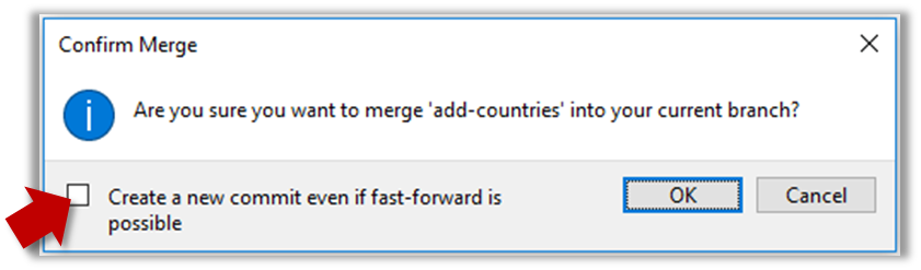
Mac:
Trigger the branch operation using the following menu button:
In the next dialog, tick the following option:
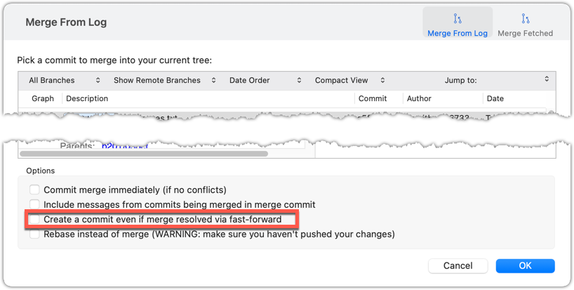
To permanently prevent fast-forwarding:
- Go to Sourcetree
Settings. - Navigate to the
Gitsection. - Tick the box
Do not fast-forward when merging, always create commit.
A squash merge combines all the changes from a branch into a single commit on the receiving branch, without preserving the full commit history of the branch being merged. This is especially useful when the feature branch contains many small or experimental commits that would clutter the main branch’s history. By squashing, you retain the final state of the changes while presenting them as one cohesive unit, making the project history easier to read and manage. It also helps maintain a linear, simplified commit log on the main branch.
gitGraph BT:
%%{init: { 'theme': 'default', 'gitGraph': {'mainBranchName': 'master'}} }%%
commit id: "[HEAD → master] m1"
branch feature
checkout feature
commit id: "f1"
commit id: "[feature] f2"
→
[squash merge...]
gitGraph BT:
%%{init: { 'theme': 'default', 'gitGraph': {'mainBranchName': 'master'}} }%%
commit id: "m1"
branch feature
checkout feature
commit id: "f1"
commit id: "[feature] f2"
checkout master
commit id: "[HEAD → master] s1 (same as f1+f2)" type: HIGHLIGHT
In the example above, the branch feature has been squash merged onto the master branch, creating a single 'squashed' commit s1 that combines the all commits in feature branch.
When merging branches, you need to guide Git on how to resolve conflicting changes in different branches.
A merge conflict happens when Git can't automatically combine changes from two branches because the same parts of a file were modified differently in each branch. When this happens, Git pauses the merge and marks the conflicting sections in the affected files so you can resolve them yourself. Once you've reviewed and fixed the conflicts, you can tell Git they're resolved and complete the merge.
More generally, a conflict occurs when Git cannot automatically reconcile different changes made to the same part of a file -- branch merge conflicts is just one example.
In this hands-on practical, we simulate a merge conflict and use it to learn how to resolve merge conflicts. You can use any repo with at least one commit in the master branch for this.
1 Start a branch named fix1 in the repo. Create a commit that adds a line with some text to one of the files.
2 Switch back to master branch. Create a commit with a conflicting change i.e., it adds a line with some different text in the exact location the previous line was added.
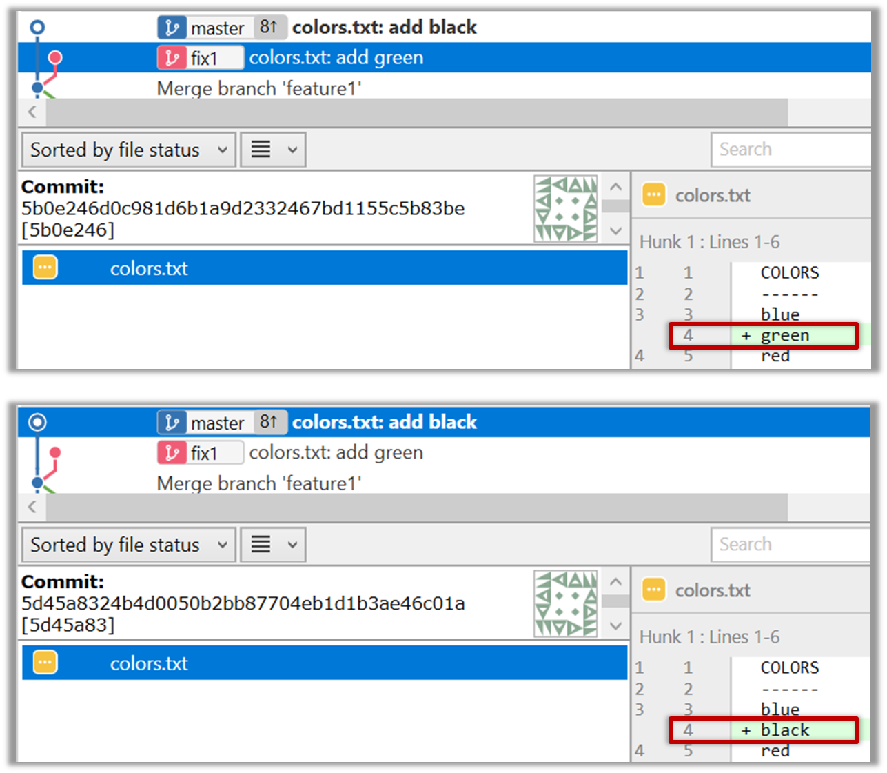
3 Try to merge the fix1 branch onto the master branch. Git will pause mid-way during the merge and report a merge conflict. If you open the conflicted file, you will see something like this:
COLORS
------
blue
<<<<<< HEAD
black
=======
green
>>>>>> fix1
red
white
4 Observe how the conflicted part is marked between a line starting with <<<<<< and a line starting with >>>>>>, separated by another line starting with =======.
Highlighted below is the conflicting part that is coming from the master branch:
blue
<<<<<< HEAD
black
=======
green
>>>>>> fix1
red
This is the conflicting part that is coming from the fix1 branch:
blue
<<<<<< HEAD
black
=======
green
>>>>>> fix1
red
5 Resolve the conflict by editing the file. Let us assume you want to keep both lines in the merged version. You can modify the file to be like this:
COLORS
------
blue
black
green
red
white
6 Stage the changes, and commit. You have now successfully resolved the merge conflict.
done!
Branches can be renamed, for example, to fix a mistake in the branch name.
Local branches can be renamed easily. Renaming a branch simply changes the branch reference (i.e., the name used to identify the branch) — it is just a cosmetic change.
First, create the repo samplerepo-books for this hands-on practical, by running the following commands in your terminal.
mkdir samplerepo-books
cd samplerepo-books
git init
echo "Horror Stories" >> horror.txt
git add .
git commit -m "Add horror.txt"
git switch -c textbooks
echo "Textbooks" >> textbooks.txt
git add .
git commit -m "Add textbooks.txt"
git switch -c fantasy master
echo "Fantasy Books" >> fantasy.txt
git add .
git commit -m "Add fantasy.txt"
git checkout master
git merge --no-ff -m "Merge branch textbooks" textbooks
The above should give you a repo similar to the revision graph given below, on the left.
gitGraph BT:
%%{init: { 'theme': 'default', 'gitGraph': {'mainBranchName': 'master'}} }%%
commit id: "m1"
branch textbooks
checkout textbooks
commit id: "[textbooks] t1"
checkout master
branch fantasy
checkout fantasy
commit id: "[fantasy] f1"
checkout master
merge textbooks id: "[HEAD → master] mc1"
→
[rename branches]
gitGraph BT:
%%{init: { 'theme': 'default', 'gitGraph': {'mainBranchName': 'master'}} }%%
commit id: "m1"
branch study-books
checkout study-books
commit id: "[study-books] t1"
checkout master
branch fantasy-books
checkout fantasy-books
commit id: "[fantasy-books] f1"
checkout master
merge study-books id: "[HEAD → master] mc1"
Now, rename the fantasy branch to fantasy-books. Similarly, rename textbooks branch to study-books. The outcome should be similar to the revision graph above, on the right.
To rename a branch, use the git branch -m <current-name> <new-name> command (-m stands for 'move'):
git branch -m fantasy fantasy-books
git branch -m textbooks study-books
git log --one-line --decorate --graph --all # verify the changes
* 443132a (HEAD -> master) Merge branch textbooks
|\
| * 4969163 (study-books) Add textbooks.txt
|/
| * 0586ee1 (fantasy-books) Add fantasy.txt
|/
* 7f28f0e Add horror.txt
Note these additional switches to the log command:
--all: Shows all branches, not just the current branch.--graph: Shows a graph-like visualisation (notice how*is used to indicate a commit, and branches are indicated using vertical lines.
Right-click on the branch name and choose Rename.... Provide the new branch name in the next dialog.
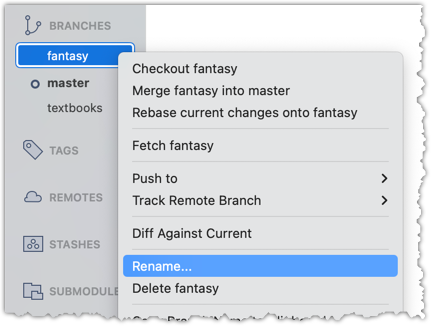
done!
Branches can be deleted, to get rid of them when they are no longer needed.
Deleting a branch deletes the corresponding branch ref from the revision history (it does not delete any commits). The impact of the loss of the branch ref depends on whether the branch has been merged.
When you delete a branch that has been merged, the commits of the branch will still exist in the history and will be safe. Only the branch ref is lost.
gitGraph BT:
%%{init: { 'theme': 'default', 'gitGraph': {'mainBranchName': 'master'}} }%%
commit id: "m1"
branch bug-fix
checkout bug-fix
commit id: "[bug-fix] b1"
checkout master
merge bug-fix id: "[HEAD → master] mc1"
→
[delete branch bug-fix]
gitGraph BT:
%%{init: { 'theme': 'default', 'gitGraph': {'mainBranchName': 'master'}} }%%
commit id: "m1"
branch _
checkout _
commit id: "b1"
checkout master
merge _ id: "[HEAD → master] mc1"
In the above example, the only impact of the deletion is the loss of the branch ref bug-fix. All commits remain reachable (via the master branch), and there is no other impact on the revision history.
In fact, some prefer to delete the branch soon after merging it, to reduce branch references cluttering up the revision history.
When you delete a branch that has not been merged, the loss of the branch ref can render some commits unreachable (unless you know their commit IDs or they are reachable through other refs), putting them at risk of being lost eventually.
gitGraph BT:
%%{init: { 'theme': 'default', 'gitGraph': {'mainBranchName': 'master'}} }%%
commit id: "[HEAD → master] m1"
branch bug-fix
checkout bug-fix
commit id: "[bug-fix] b1"
checkout master
→
[delete branch bug-fix]
gitGraph BT:
%%{init: { 'theme': 'default', 'gitGraph': {'mainBranchName': 'master'}} }%%
commit id: "[HEAD → master] m1"
branch _
checkout _
commit id: "b1"
checkout master
In the above example, the commit b1 is no longer reachable, unless we know its commit ID (i.e., the SHA).
SIDEBAR: What makes a commit 'unreachable'?
Recall that a commit only has a pointer to its parent commit (not its descendent commits).
A commit is considered reachable if you can get to it by starting at a branch, tag, or other ref and walking backward through its parent commits. This is the normal state for commits — they are part of the visible history of a branch or tag.
When no branch, tag, or ref points to a commit (directly or indirectly), it becomes unreachable. This often happens when you delete a branch or rewrite history (e.g., with reset or rebase), leaving some commits "orphaned" (or "dangling") without a ref pointing to them.
In the example below, C4 is unreachable (i.e., cannot be reached by starting at any of the three refs: v1.0 or master or ←HEAD), but the other three are all reachable.
Unreachable commits are not deleted immediately — Git keeps them for a while before cleaning them up. By default, Git retains unreachable commits for at least 30 days, during which they can still be recovered if you know their SHA. After that, they will be garbage-collected, and will be lost for good.
Preparation First, create the repo samplerepo-books-2 for this hands-on practical, by running the following commands in your terminal.
mkdir samplerepo-books-2
cd samplerepo-books-2
git init
echo "Horror Stories" >> horror.txt
git add .
git commit -m "Add horror.txt"
git switch -c textbooks
echo "Textbooks" >> textbooks.txt
git add .
git commit -m "Add textbooks.txt"
git switch -c fantasy master
echo "Fantasy Books" >> fantasy.txt
git add .
git commit -m "Add fantasy.txt"
git checkout master
git merge --no-ff -m "Merge branch textbooks" textbooks
1 Delete the (the merged) textbooks branch.
Use the git branch -d <branch> command to delete a local branch 'safely' -- this command will fail if the branch has unmerged changes.
git branch -d textbooks
git log --oneline --decorate --graph --all # check the current revision graph
* 443132a (HEAD -> master) Merge branch textbooks
|\
| * 4969163 Add textbooks.txt
|/
| * 0586ee1 (fantasy) Add fantasy.txt
|/
* 7f28f0e Add horror.txt
Right-click on the branch name and choose Delete <branch>:
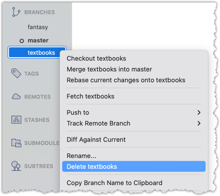
In the next dialog, click OK:
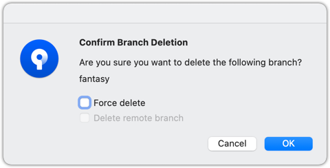
Observe that all commits remain. The only missing thing is the textbook ref.
2 Make a copy of the SHA of the tip of the (unmerged) fantasy branch.
3 Delete the fantasy branch..
Attempt to delete the branch. It should fail, as shown below:
git branch -d fantasy
error: the branch 'fantasy' is not fully merged
hint: If you are sure you want to delete it, run 'git branch -D fantasy'
As also hinted by the error message, you can replace the -d with -D to 'force' the deletion.
git branch -D fantasy
Now, check the revision graph:
git log --oneline --decorate --graph --all
* 443132a (HEAD -> master) Merge branch textbooks
|\
| * 4969163 Add textbooks.txt
|/
* 7f28f0e Add horror.txt
Attempt to delete the branch as you did before. It will fail because the branch has unmerged commits.
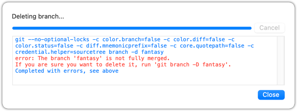
Try again but this time, tick the Force delete option, which will force Git to delete the unmerged branch:
Observe how the branch ref fantasy is gone, together with any unmerged commits on it.
4 Attempt to view the 'unreachable' commit whose SHA you noted in step 2.
e.g., git show 32b34fb (use the SHA you copied earlier)
Observe how the commit still exists and still reachable using the commit ID, although not reachable by other means, and not visible in the revision graph.
done!
Merging is one way to keep one branch synchronise itself with changes introduced into another.
When working in parallel branches, you’ll often need to sync (short for synchronise) one branch with changes made in another. For example, while developing a feature in one branch, you might want to bring in a recent bug fix from another branch that your branch doesn’t yet have.
The simplest way to sync branches is to merge — that is, to sync a branch b1 with changes from another branch b2, you merge b2 into b1. In fact, you can merge them periodically to keep one branch up to date with the other.
gitGraph
%%{init: { 'theme': 'default', 'gitGraph': {'mainBranchName': 'master'}} }%%
commit id: "m1"
branch bug-fix
branch feature
commit id: "f1"
checkout master
checkout bug-fix
commit id: "b1"
checkout master
merge bug-fix
checkout feature
merge master id: "mc1"
commit id: "f2"
checkout master
commit id: "m2"
checkout feature
merge master id: "mc2"
checkout master
commit id: "m3"
checkout feature
commit id: "[feature] f3"
checkout master
commit id: "[HEAD → master] m4"
In the example above, you can see how the feature branch is merging the master branch periodically to keep itself in sync with the changes being introduced to the master branch.
Rebasing is another way to synchronise one branch with another.
Rebasing is another way to synchronise one branch with another, while keeping the history cleaner and more linear. Instead of creating a merge commit to combine the branches, rebasing moves the entire sequence of commits from your branch and "replays" them on top of another branch. This effectively relocates the base of your branch to the tip of the other branch (i.e., 're-base', hence the name), as if you had started your work from there in the first place.
Rebasing is especially useful when you want to update your branch with the latest changes from a main branch, but you prefer an uncluttered history with fewer merge commits.
Suppose we have the following revision graph, and we want to sync the feature branch with master, so that changes in commit m2 become visible to the feature branch.
gitGraph
%%{init: { 'theme': 'default', 'gitGraph': {'mainBranchName': 'master'}} }%%
commit id: "m1"
branch feature
checkout feature
commit id: "f1"
checkout master
commit id: "[master] m2"
checkout feature
commit id: "[HEAD → feature] f2"
If we merge the master branch to the feature branch as given below, m2 become visible to feature branch. However, it creates a merge commit.
gitGraph
%%{init: { 'theme': 'default', 'gitGraph': {'mainBranchName': 'master'}} }%%
commit id: "m1"
branch feature
checkout feature
commit id: "f1"
checkout master
commit id: "[master] m2"
checkout feature
commit id: "f2"
merge master id: "[HEAD → feature] mc1"
Instead of merging, if we rebased the feature branch on the master branch, we would get the following.
gitGraph
%%{init: { 'theme': 'default', 'gitGraph': {'mainBranchName': 'master'}} }%%
commit id: "m1"
checkout master
commit id: "[branch: master] m2"
branch feature
checkout feature
commit id: "f1a"
commit id: "[HEAD → feature] f2a"
Note how the rebasing changed the base of the feature branch from m1 to m2. As a result, changes done in m2 are now visible to the feature branch. But there is no merge commit, and the revision graph is simpler.
Also note how the first commit in the feature branch, previously shown as f1, is now shown as f1a after the rebase. Although both commits contain the same changes, other details — such as the parent commit — are different, making them two distinct Git objects with different SHA values. Similarly, f2 and f2a are also different. Thus, the history of the entire feature branch has changed after the rebase.
Because rebasing rewrites the commit history of your branch, it's important to use it carefully. You should avoid rebasing branches that you’ve already shared with others, because rewriting published history can cause confusion and conflicts for anyone else working on the same branch.
Cherry-picking is a Git operation that copies over a specific commit from one branch to another.
Cherry-picking is another way to synchronise branches, by applying specific commits from one branch onto another.
Unlike merging or rebasing — which bring over all changes since the branches diverged — cherry-picking lets you choose individual commits and apply just those, one at a time, to your current branch. This is useful when you want to bring over a bug fix or a small feature from another branch without merging the entire branch history.
Because cherry-picking copies only the chosen commits, it creates new commits on your branch with the same changes but different SHA values.
Suppose we have the following revision graph, and we want to bring over the changes introduced in m3 (in the master branch) onto the feature branch.
gitGraph
%%{init: { 'theme': 'default', 'gitGraph': {'mainBranchName': 'master'}} }%%
commit id: "m1"
branch feature
checkout feature
commit id: "f1"
checkout master
commit id: "m2"
commit id: "m3" type: HIGHLIGHT
commit id: "[master] m4"
checkout feature
commit id: "[HEAD → feature] f2"
After cherry-picking m3 onto the feature branch, the revision graph should look like the following:
gitGraph
%%{init: { 'theme': 'default', 'gitGraph': {'mainBranchName': 'master'}} }%%
commit id: "m1"
branch feature
checkout feature
commit id: "f1"
checkout master
commit id: "m2"
commit id: "m3" type: HIGHLIGHT
commit id: "[master] m4"
checkout feature
commit id: "f3"
commit id: "[HEAD → feature] m3a" type: HIGHLIGHT
Note how it makes the changes done in m3 available (from now on) in the feature branch, with minimal changes to the revison graph.
Also note that the new commit m3a contains the same changes as m3, but it will a different Git object with a different SHA value.
Cherry-picking is another Git operation that can result in conflicts i.e., if the changes in the cherry-picked commit conflicts with the changes in the receiving branch.
Local branches can be replicated in a remote.
Pushing a copy of a local branches to the corresponding remote repo makes those branches available remotely.
In a previous lesson, we saw how to push the default branch to a remote repository and have Git set up tracking between the local and remote branches using a remote-tracking reference. Pushing any other local branch to a remote works the same way as pushing the default branch — you simply specify the target branch instead of the default branch. Pushing any new commits in any local branch to a corresponding remote branch is done similarly as well.
gitGraph BT:
%%{init: { 'theme': 'default', 'gitGraph': {'mainBranchName': 'master'}} }%%
commit id: "m1"
branch bug-fix
checkout master
commit id: "[origin/master][HEAD → master] m2"
checkout bug-fix
commit id: "[bug-fix] b1"
checkout master
[bug-fix branch does not exist in the remote origin]
→
gitGraph BT:
%%{init: { 'theme': 'default', 'gitGraph': {'mainBranchName': 'master'}} }%%
commit id: "m1"
branch bug-fix
checkout master
commit id: "[origin/master][HEAD → master] m2"
checkout bug-fix
commit id: "[origin/bug-fix][bug-fix] b1"
checkout master
[after pushing bug-fix branch to origin,
and setting up a remote-tracking branch]
1 Fork the samplerepo-company to your GitHub account. When doing so, un-tick the Copy the master branch only option.
After forking, go to the fork and ensure both branches (master, and track-sales) are in there.
2 Clone the fork to your computer. It should look something like this:
gitGraph BT:
%%{init: { 'theme': 'default', 'gitGraph': {'mainBranchName': 'master'}} }%%
commit id: "m1"
commit id: "m2"
branch track-sales
checkout track-sales
commit id: "[origin/track-sales] s1"
checkout master
commit id: "[origin/master][origin/HEAD][HEAD → master] m3"
The origin/HEAD remote-tracking ref indicates where the HEAD ref is in the remote origin.
3 Create a new branch hiring, and add a commit to that branch. The commit can contain any changes you want.
Here are the commands you can run in the terminal to do this step in on shot:
git switch -c hiring
echo "Receptionist: Pam" >> employees.txt
git commit -am "Add Pam to employees.txt"
gitGraph BT:
%%{init: { 'theme': 'default', 'gitGraph': {'mainBranchName': 'master'}} }%%
commit id: "m1"
commit id: "m2"
branch track-sales
checkout track-sales
commit id: "[origin/track-sales] s1"
checkout master
commit id: "[origin/master][origin/HEAD][master] m3"
branch hiring
checkout hiring
commit id: "[HEAD → hiring] h1"
The resulting revision graph should look like the one above.
4 Push the hiring branch to the remote.
You can use the usual git push <remote> -u <branch> command to push the branch to the remote, and set up a remote-tracking branch at the same time.
git push origin -u hiring
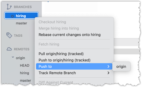
5 Verify the branch has been pushed to the remote by visiting the fork on GitHub, and looking for the origin/hiring remote-tracking ref in the local repo.
done!
Branches in a remote can be replicated in the local repo, and maintained in sync with each other.
Sometimes we need to create a local copy of a branch from a remote repository, make further changes to it, and keep it synchronised with the remote branch. Let's explore how to handle this in a few common use cases:
Use case 1: Working with branches that already existed in the remote repo when you cloned it to your computer.
When you clone a repository,
- Git checks out the default branch. You can start working on this branch immediately. This branch is tracking the default branch in the remote, which means you easily synchronise changes in this branch with the remote by pulling and pushing.
- Git also fetches all the other branches from the remote. These other branches are not immediately available as local branches, but they are visible as remote-tracking branches.
You can think of remote-tracking branches as read-only references to the state of those branches in the remote repository at the time of cloning. They allow you to see what work has been done on those branches without yet making local copies of them.
To work on one of these branches, you can create a new local branch based on the remote-tracking branch. Once you do this, your local branch will usually be configured to track the corresponding branch on the remote, so you can easily synchronise your work later.
This hands-on practical uses the same samplerepo-company repo you used in Lesson T8L1. Pushing Branches to a Remote. Fork and clone it if you haven't done that already.
1 Verify that the remote-tracking branch origin/track-sales exists in the local repo, but there is no local copy of it.
You can use the git branch -a command to list all local and tracking branches.
git branch -a
* hiring
master
remotes/origin/HEAD -> origin/master
remotes/origin/hiring
remotes/origin/master
remotes/origin/track-sales
The * in the output above indicates the currently active branch.
Note how there is no track-sales in the list of branches (i.e., no local branch named track-sales), but there is a remotes/origin/track-sales (i.e., the remote-tracking branch)
Observe how the branch track-sales appear under REMOTES → origin but not under BRANCHES.
2 Create a local copy of the remote branch origin/track-sales.
You can use the git switch -c <branch> <remote-branch> command for this e.g.,
git switch -c track-sales origin/track-sales
Locate the track-sales remote-tracking branch (look under REMOTES → origin), right-click, and choose Checkout....
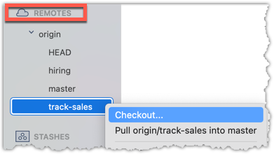
In the next dialog, choose as follows:
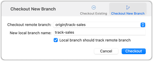
The above command/action does several things:
- Creates a new branch
track-sales. - Sets the new branch to track the remote branch
origin/track-sales, which means the local branch reftrack-saleswill also move to where theorigin/track-salesis. - Switch to the newly-created branch i.e., makes it the current branch.
3 Add a commit to the track-sales branch and push to the remote, to verify that the local branch is tracking the remote branch.
Commands to perform this step in one shot:
echo "5 reams of paper" >> sales.txt
git commit -am "Update sales.txt"
git push origin track-sales
done!
Use case 2: Working with branches that were added to the remote repository after you cloned it e.g., a branch someone else pushed to the remote after you cloned.
Simply fetch to update your local repository with information about the new branch. After that, you can create a local copy of it and work with it just as you did in Use Case 1.
Often, you'll need to delete a branch in a remote repo after it has served it purpose.
To delete a branch in a remote repository, you simply tell Git to remove the reference to that branch from the remote. This does not delete the branch from your local repository — it only removes it from the remote, so others won’t see it anymore. This is useful for cleaning up clutter in the remote repo e.g., delete old or merged branches that are no longer needed on the remote.
1 Fork the samplerepo-books to your GitHub account. When doing so, un-tick the Copy the master branch only option.
After forking, go to the fork and ensure all three branches are in there.
2 Clone the fork to your computer.
3 Create a local copy of the fantasy branch in your clone.
Follow instructions in Lesson T8L1. Pushing Branches to a Remote.
4 Delete the remote branch fantasy.
You can use the git push <remote> --delete <branch> command to delete a branch in a remote. This is like pushing changes in a branch to a remote, except we request the branch to be deleted instead by adding the --delete switch.
git push origin --delete fantasy
Locate the remote branch under REMOTES → origin, right-click on the branch name, and choose Delete...:
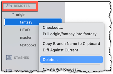
5 Verify the branch was deleted from the remote, by going to the fork on GitHub and checking the branches page https://github.com/{YOUR_USERNAME}/samplerepo-books/branches
e.g., https://github.com/johndoe/samplerepo-books/branches.
Also verify the local copy has not been deleted.
6 Restore the remote branch from the local copy.
Push the local branch to the remote, while enabling the tracking option (as if pushing the branch to the remote for the first time), as covered in Lesson T8L1. Pushing Branches to a Remote.
In the above steps, we first created a local copy of the branch before deleting it in the remote repo. Doing so is optional. You can delete a remote branch without ever checking it out locally — you just need to know its name on the remote. Deleting the remote branch directly without creating a local copy is recommended if you simply want to clean up a remote branch you no longer need.
done!
Occasionally, you might need to rename a branch in a remote repo.
You can't rename remote branches in place. Instead, you create a new branch with the desired name and delete the old one. This involves renaming your local branch to the new name, pushing it to the remote (which effectively creates a new remote branch), and then removing the old branch from the remote. This ensures the remote reflects the updated name while preserving the commit history and any work already done on the branch.
This hands-on practical can be done using the fork and the clone of the samplerepo-books that you created in Lesson T8L3. Deleting Branches from a Remote.
Rename the branch fantasy in the remote (i.e., your fork) to fantasy-books.
Here are the steps:
- Ensure you are in the
masterbranch. - Create a local copy of the remote-tracking branch
origin/fantasy. - Rename the local copy of the branch to
fantasy-books. - Push the renamed local branch to the remote, while setting up tracking for the branch as well.
- Delete the remote branch.
git switch master # ensure you are on the master branch
git switch -c fantasy origin/fantasy # create a local copy, tracking the remote branch
git branch -m fantasy fantasy-books # rename local branch
git push -u origin fantasy-books # push the new branch to remote, and set it to track
git push origin --delete fantasy # delete the old branch
You can run the git log --oneline --decorate --graph --all to check the revision graph after each step. The final outcome should be something like the below:
* 355915c (HEAD -> fantasy-books, origin/fantasy-books) Add fantasy.txt
| * 027b2b0 (origin/master, origin/HEAD, master) Merge branch textbooks
|/|
| * a6ebaec (origin/textbooks) Add textbooks.txt
|/
* d462638 Add horror.txt
Perform the above steps (each step was covered in a previous lesson).
done!
A pull request (PR for short) is a mechanism for contributing code to a remote repo i.e., "I'm requesting you to pull my proposed changes to your repo". It's feature provided by RCS platforms such as GitHub. For this to work, the two repos must have a shared history. The most common case is sending PRs from a fork to its repo.
Suppose you want to propose some changes to a GitHub repo (e.g., samplerepo-pr-practice) as a pull request (PR).
samplerepo-pr-practice is an unmonitored repo you can use to practice working with PRs. Feel free to send PRs to it.
Given below is a scenario you can try in order to learn how to create PRs:
1. Fork the repo onto your GitHub account.
2. Clone it onto your computer.
3. Commit your changes e.g., add a new file with some contents and commit it.
- Option A - Commit changes to the
masterbranch - Option B - Commit to a new branch e.g., create a branch named
add-intro(remember to switch to themasterbranch before creating a new branch) and add your commit to it.
4. Push the branch you updated (i.e., master branch or the new branch) to your fork, as explained here.
5. Initiate the PR creation:
Go to your fork.
Click on the Pull requests tab followed by the New pull request button. This will bring you to the
Compare changespage.Set the appropriate target repo and the branch that should receive your PR, using the
base repositoryandbasedropdowns. e.g.,
base repository: se-edu/samplerepo-pr-practice base: masterNormally, the default value shown in the dropdown is what you want but in case your fork has , the default may not be what you want.
Indicate which repo:branch contains your proposed code, using the
head repositoryandcomparedropdowns. e.g.,
head repository: myrepo/samplerepo-pr-practice compare: master
6. Verify the proposed code: Verify that the diff view in the page shows the exact change you intend to propose. If it doesn't, as necessary.
7. Submit the PR:
Click the Create pull request button.
Fill in the PR name and description e.g.,
Name:Add an introduction to the README.md
Description:Add some paragraph to the README.md to explain ... Also add a heading ...If you want to indicate that the PR you are about to create is 'still work in progress, not yet ready', click on the dropdown arrow in the Create pull request button and choose
Create draft pull requestoption.Click the Create pull request button to create the PR.
Go to the receiving repo to verify that your PR appears there in the
Pull requeststab.
The next step of the PR lifecycle is the PR review. The members of the repo that received your PR can now review your proposed changes.
- If they like the changes, they can merge the changes to their repo, which also closes the PR automatically.
- If they don't like it at all, they can simply close the PR too i.e., they reject your proposed change.
- In most cases, they will add comments to the PR to suggest further changes. When that happens, GitHub will notify you.
You can update the PR along the way too. Suppose PR reviewers suggested a certain improvement to your proposed code. To update your PR as per the suggestion, you can simply modify the code in your local repo, commit the updated code to the same branch as before, and push to your fork as you did earlier. The PR will auto-update accordingly.
Sending PRs using the master branch is less common than sending PRs using separate branches. For example, suppose you wanted to propose two bug fixes that are not related to each other. In that case, it is more appropriate to send two separate PRs so that each fix can be reviewed, refined, and merged independently. But if you send PRs using the master branch only, both fixes (and any other change you do in the master branch) will appear in the PRs you create from it.
To create another PR while the current PR is still under review, create a new branch (remember to switch back to the master branch first), add your new proposed change in that branch, and create a new PR following the steps given above.
It is possible to create PRs within the same repo e.g., you can create a PR from branch feature-x to the master branch, within the same repo. Doing so will allow the code to be reviewed by other developers (using PR review mechanism) before it is merged.
Problem: merge conflicts in ongoing PRs, indicated by the message This branch has conflicts that must be resolved. That means the upstream repo's master branch has been updated in a way that the PR code conflicts with that master branch. Here is the standard way to fix this problem:
- Pull the
masterbranch from the upstream repo to your local repo.git checkout master git pull upstream master - In the local repo, attempt to merge the
masterbranch (that you updated in the previous step) onto the PR branch, in order to bring over the new code in themasterbranch to your PR branch.git checkout pr-branch # assuming pr-branch is the name of branch in the PR git merge master - The merge you are attempting will run into a merge conflict, due to the aforementioned conflicting code in the
masterbranch. Resolve the conflict manually (this topic is covered elsewhere), and complete the merge. - Push the PR branch to your fork. As the updated code in that branch no longer is conflicting with the
masterbranch, the merge conflict alert in the PR will go away automatically.
The PR review stage is a dialog between the PR author and members of the repo that received the PR, in order to refine and eventually merge the PR.
Given below are some steps you can follow when reviewing a PR.
1. Locate the PR:
- Go to the GitHub page of the repo.
- Click on the Pull requests tab.
- Click on the PR you want to review.
2. Read the PR description. It might contain information relevant to reviewing the PR.
3. Click on the Files changed tab to see the diff view.
You can use the following setting to try the two different views available and pick the one you like.
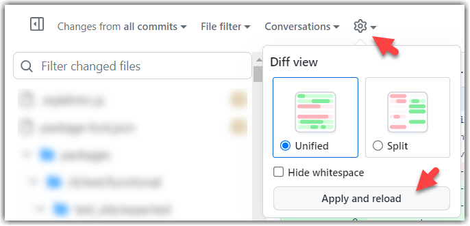
4. Add review comments:
- Hover over the line you want to comment on and click on the icon that appears on the left margin. That should create a text box for you to enter your comment.
- To give a comment related to multiple lines, click-and-drag the icon. The result will look like this:
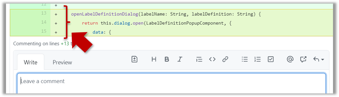
- To give a comment related to multiple lines, click-and-drag the icon. The result will look like this:
- Enter your comment.
- This page @SE-EDU/guides has some best practices PR reviewers can follow.
- To suggest an in-line code change, click on this icon:
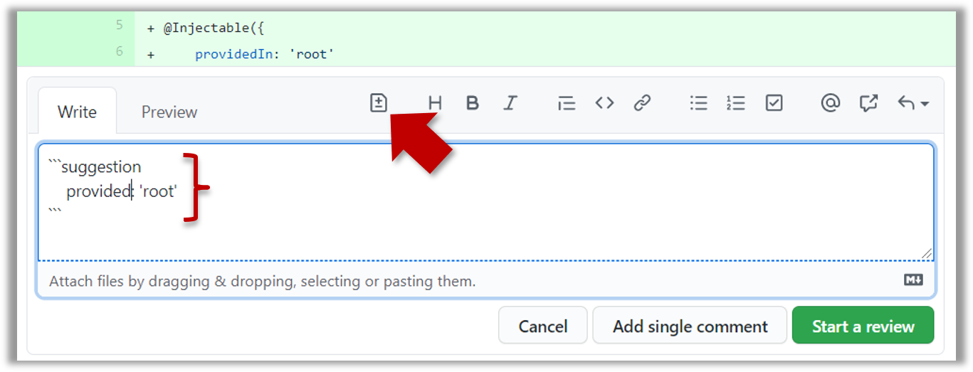
After that, you can proceed to edit thesuggestioncode block generated by GitHub (as seen in the screenshot above).
The comment will look like this to the viewers:
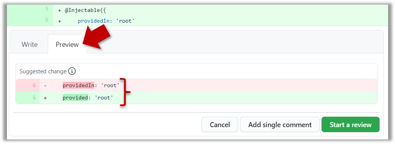
- After typing in the comment, click on the Start a review button (not the Add single comment button. This way, your comment is saved but not visible to others yet. It will be visible to others only when you have finished the entire review.
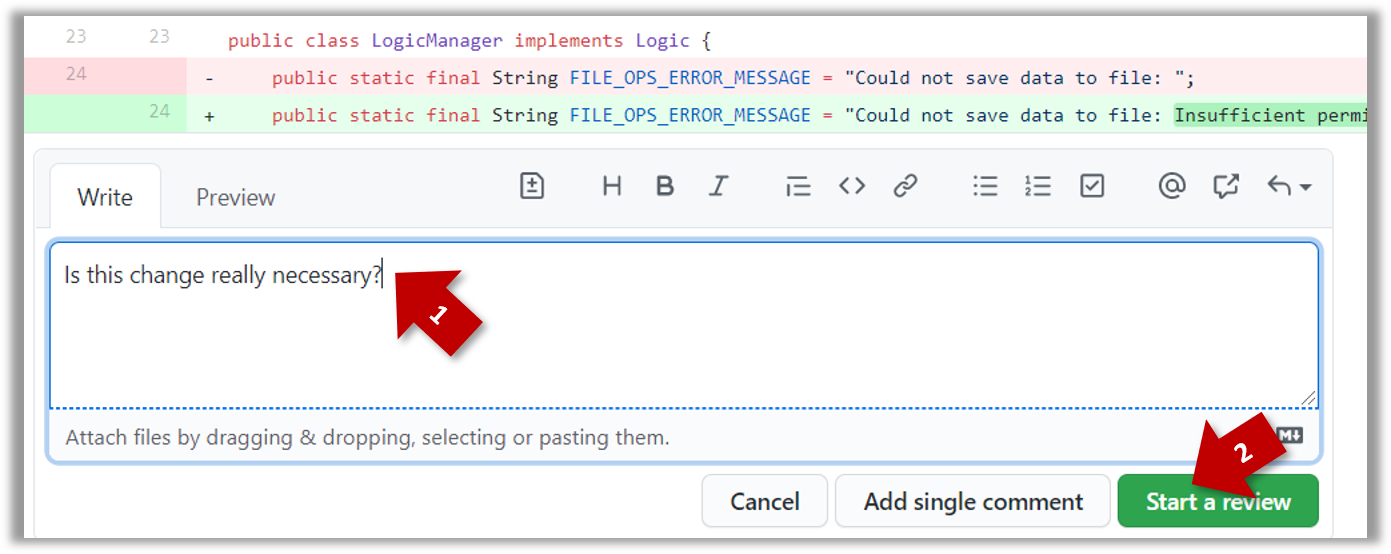
- Repeat the above steps to add more comments.
5. Submit the review:
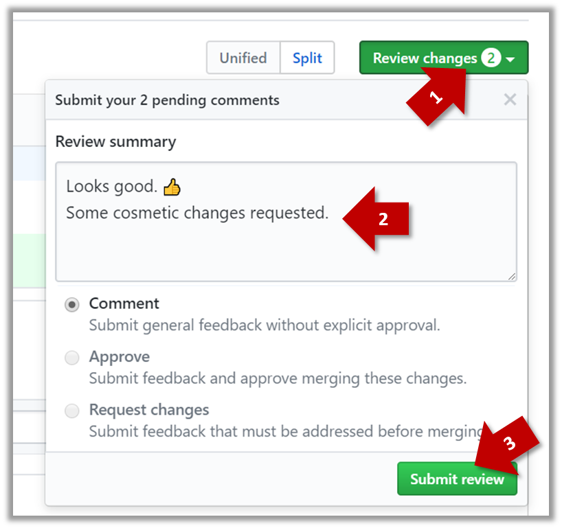
- When there are no more comments to add, click on the Review changes button (on the top right of the diff page).
- Type in an overall comment about the PR, if any. e.g.,
Overall, I found your code easy to read for the most part except a few places where the nesting was too deep. I noted a few minor coding standard violations too. Some of the classes are getting quite long. Consider splitting into smaller classes if that makes sense.LGTMis often used in such overall comments, to indicateLooks good to me(orLooks good to merge).
nit(as in nit-picking) is another such term, used to indicate minor flaws e.g.,LGTM. Just a few nits to fix.. - Choose
Approve,Comment, orRequest changesoption as appropriate and click on the Submit review button.
Let's look at the steps involved in merging a PR, assuming the PR has been reviewed, refined, and approved for merging already.
Preparation: If you would like to try merging a PR yourself, you can create a dummy PR in the following manner.
- Fork any repo (e.g., samplerepo-pr-practice).
- Clone in to your computer.
- Create a new branch e.g., (
feature1) and add some commits to it. - Push the new branch to the fork.
- Create a PR from that branch to the
masterbranch in your fork. Yes, it is possible to create a PR within the same repo.
1. Locate the PR to be merged in your repo's GitHub page.
2. Click on the Conversation tab and scroll to the bottom. You'll see a panel containing the PR status summary.
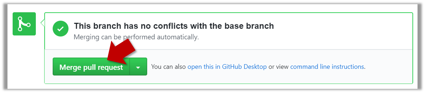
3. If the PR is not merge-able in the current state, the Merge pull request will not be green. Here are the possible reasons and remedies:
- Problem: The PR code is out-of-date, indicated by the message This branch is out-of-date with the base branch. That means the repo's
masterbranch has been updated since the PR code was last updated.- If the PR author has allowed you to update the PR and you have sufficient permissions, GitHub will allow you to update the PR simply by clicking the Update branch on the right side of the 'out-of-date' error message. If that option is not available, post a message in the PR requesting the PR author to update the PR.
- Problem: There are merge conflicts, indicated by the message This branch has conflicts that must be resolved. That means the repo's
masterbranch has been updated since the PR code was last updated, in a way that the PR code conflicts with the currentmasterbranch. Those conflicts must be resolved before the PR can be merged.- If the conflicts are simple, GitHub might allow you to resolve them using the Web interface.
- If that option is not available, post a message in the PR requesting the PR author to update the PR.
4. Merge the PR by clicking on the Merge pull request button, followed by the Confirm merge button. You should see a Pull request successfully merged and closed message after the PR is merged.
- You can choose between three merging options by clicking on the down-arrow in the Merge pull request button. If you are new to Git and GitHub, the
Create merge commitoption is recommended.
Next, sync your local repos (and forks). Merging a PR simply merges the code in the upstream remote repository in which it was merged. The PR author (and other members of the repo) needs to pull the merged code from the upstream repo to their local repos and push the new code to their respective forks to sync the fork with the upstream repo.
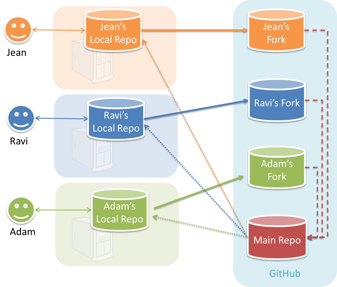
In the forking workflow, the 'official' version of the software is kept in a remote repo designated as the 'main repo'. All team members fork the main repo and create pull requests from their fork to the main repo.
To illustrate how the workflow goes, let’s assume Jean wants to fix a bug in the code. Here are the steps:
- Jean creates a separate branch in her local repo and fixes the bug in that branch.
Common mistake: Doing the proposed changes in themasterbranch -- if Jean does that, she will not be able to have more than one PR open at any time because any changes to themasterbranch will be reflected in all open PRs. - Jean pushes the branch to her fork.
- Jean creates a pull request from that branch in her fork to the main repo.
- Other members review Jean’s pull request.
- If reviewers suggested any changes, Jean updates the PR accordingly.
- When reviewers are satisfied with the PR, one of the members (usually the team lead or a designated 'maintainer' of the main repo) merges the PR, which brings Jean’s code to the main repo.
- Other members, realizing there is new code in the upstream repo, sync their forks with the new upstream repo (i.e., the main repo). This is done by pulling the new code to their own local repo and pushing the updated code to their own fork. If there are unmerged branches in the local repo, they can be updated too e.g., by merging the new
masterbranch to each of them.
Possible mistake: Creating another 'reverse' PR from the team repo to the team member's fork to sync the member's fork with the merged code. PRs are meant to go from downstream repos to upstream repos, not in the other direction.
One main benefit of this workflow is that it does not require most contributors to have write permissions to the main repository. Only those who are merging PRs need write permissions. The main drawback of this workflow is the extra overhead of sending everything through forks.
You can follow the steps in the simulation of a forking workflow given below to learn how to follow such a workflow.
This activity is best done as a team.
Step 1. One member: set up the team org and the team repo.
Create a GitHub organization for your team, if you don't have one already. The org name is up to you. We'll refer to this organization as team org from now on.
Add a team called
developersto your team org.Add team members to the
developersteam.Fork se-edu/samplerepo-workflow-practice to your team org. We'll refer to this as the team repo.
Add the forked repo to the
developersteam. Give write access.
Step 2. Each team member: create PRs via own fork.
Fork that repo from your team org to your own GitHub account.
Create a branch named
add-{your name}-info(e.g.add-johnTan-info) in the local repo.Add a file
yourName.mdinto themembersdirectory (e.g.,members/johnTan.md) containing some info about you into that branch.Push that branch to your fork.
Create a PR from that branch to the
masterbranch of the team repo.
Step 3. For each PR: review, update, and merge.
[A team member (not the PR author)] Review the PR by adding comments (can be just dummy comments).
[PR author] Update the PR by pushing more commits to it, to simulate updating the PR based on review comments.
[Another team member] Approve and merge the PR using the GitHub interface.
[All members] Sync your local repo (and your fork) with upstream repo. In this case, your upstream repo is the repo in your team org.
- The basic mechanism for this has two steps (which you can do using Git CLI or any Git GUI):
(1) First, pull from the upstream repo -- this will update your clone with the latest code from the upstream repo.
If there are any unmerged branches in your local repo, you can update them too e.g., you can merge the newmasterbranch to each of them.
(2) Then, push the updated branches to your fork. This will also update any PRs from your fork to the upstream repo. - Some alternatives mechanisms to achieve the same can be found in this GitHub help page.
If you are new to Git, we recommend that you use the above two-step mechanism instead, so that you get a better view of what's actually happening behind the scene.
- The basic mechanism for this has two steps (which you can do using Git CLI or any Git GUI):
Step 4. Create conflicting PRs.
[One member]: Update README: In the
masterbranch, remove John Doe and Jane Doe from theREADME.md, commit, and push to the main repo.[Each team member] Create a PR to add yourself under the
Team Memberssection in theREADME.md. Use a new branch for the PR e.g.,add-johnTan-name.
Step 5. Merge conflicting PRs one at a time. Before merging a PR, you’ll have to resolve conflicts.
[Optional] A member can inform the PR author (by posting a comment) that there is a conflict in the PR.
[PR author] Resolve the conflict locally:
- Pull the
masterbranch from the repo in your team org. - Merge the pulled
masterbranch to your PR branch. - Resolve the merge conflict that crops up during the merge.
- Push the updated PR branch to your fork.
- Pull the
[Another member or the PR author]: Merge the de-conflicted PR: When GitHub does not indicate a conflict anymore, you can go ahead and merge the PR.
Project Planning
A Work Breakdown Structure (WBS) depicts information about tasks and their details in terms of subtasks. When managing projects, it is useful to divide the total work into smaller, well-defined units. Relatively complex tasks can be further split into subtasks. In complex projects, a WBS can also include prerequisite tasks and effort estimates for each task.
The high level tasks for a single iteration of a small project could look like the following:
| Task ID | Task | Estimated Effort | Prerequisite Task |
|---|---|---|---|
| A | Analysis | 1 man day | - |
| B | Design | 2 man day | A |
| C | Implementation | 4.5 man day | B |
| D | Testing | 1 man day | C |
| E | Planning for next version | 1 man day | D |
The effort is traditionally measured in man hour/day/month i.e., work that can be done by one person in one hour/day/month. The Task ID is a label for easy reference to a task. Simple labeling is suitable for a small project, while a more informative labeling system can be adopted for bigger projects.
An example WBS for a game development project.
| Task ID | Task | Estimated Effort | Prerequisite Task |
|---|---|---|---|
| A | High level design | 1 man day | - |
| B |
Detail design
|
2 man day
| A |
| C |
Implementation
|
4.5 man day
|
|
| D | System Testing | 1 man day | C |
| E | Planning for next version | 1 man day | D |
All tasks should be well-defined. In particular, it should be clear as to when the task will be considered done.
Some examples of ill-defined tasks and their better-defined counterparts:
| Bad | Better |
|---|---|
| more coding | implement component X |
| do research on UI testing | find a suitable tool for testing the UI |
A milestone is the end of a stage which indicates significant progress. You should take into account dependencies and priorities when deciding on the features to be delivered at a certain milestone.
Each intermediate product release is a milestone.
In some projects, it is not practical to have a very detailed plan for the whole project due to the uncertainty and unavailability of required information. In such cases, you can use a high-level plan for the whole project and a detailed plan for the next few milestones.
Milestones for the Minesweeper project, iteration 1
| Day | Milestones |
|---|---|
| Day 1 | Architecture skeleton completed |
| Day 3 | ‘new game’ feature implemented |
| Day 4 | ‘new game’ feature tested |
A buffer is time set aside to absorb any unforeseen delays. It is very important to include buffers in a software project schedule because effort/time estimations for software development are notoriously hard. However, do not inflate task estimates to create hidden buffers; have explicit buffers instead. Reason: With explicit buffers, it is easier to detect incorrect effort estimates which can serve as feedback to improve future effort estimates.
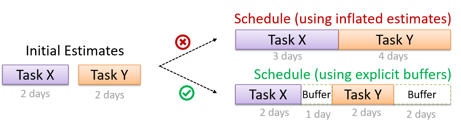
Keeping track of project tasks (who is doing what, which tasks are ongoing, which tasks are done etc.) is an essential part of project management. In small projects, it may be possible to keep track of tasks using simple tools such as online spreadsheets or general-purpose/light-weight task tracking tools such as Trello. Bigger projects need more sophisticated task tracking tools.
Issue trackers (sometimes called bug trackers) are commonly used to track task assignment and progress. Most online project management software such as GitHub, SourceForge, and BitBucket come with an integrated issue tracker.
A screenshot from the Jira Issue tracker software (Jira is part of the BitBucket project management tool suite):
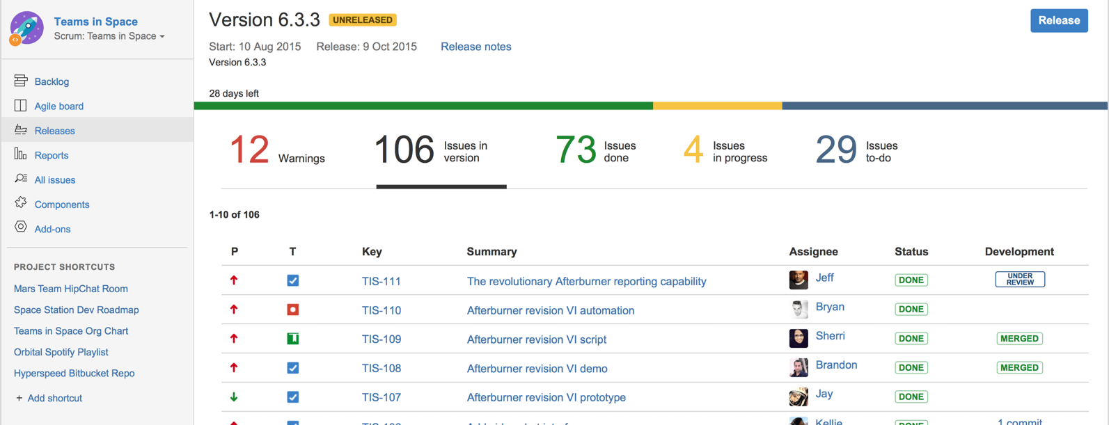
A Gantt chart is a 2-D bar-chart, drawn as time vs tasks (represented by horizontal bars).
A sample Gantt chart:
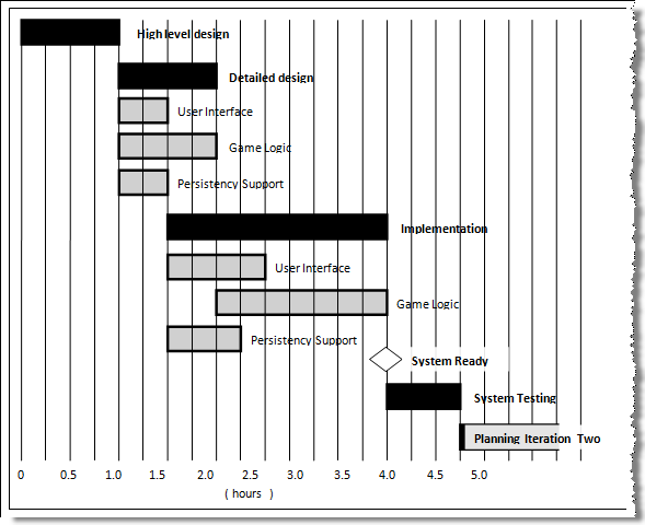
In a Gantt chart, a solid bar represents the main task, which is generally composed of a number of subtasks, shown as grey bars. The diamond shape indicates an important deadline/deliverable/milestone.
A PERT (Program Evaluation Review Technique) chart uses a graphical technique to show the order/sequence of tasks. It is based on the simple idea of drawing a directed graph in which:
- Nodes or vertices capture the effort estimations of tasks, and
- Arrows depict the precedence between tasks
An example PERT chart for a simple software project
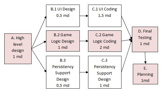
md = man days
A PERT chart can help determine the following important information:
- The order of tasks. In the example above,
Final Testingcannot begin until all coding of individual subsystems have been completed. - Which tasks can be done concurrently. In the example above, the various subsystem designs can start independently once the
High level designis completed. - The shortest possible completion time. In the example above, there is a path (indicated by the shaded boxes) from start to end that determines the shortest possible completion time.
- The Critical Path. In the example above, the shaded path is also the critical path.
Critical path is the path in which any delay can directly affect the project duration. It is important to ensure tasks on the critical path are completed on time.
Teamwork
Given below are three commonly used team structures in software development. Irrespective of the team structure, it is a good practice to assign roles and responsibilities to different team members so that someone is clearly in charge of each aspect of the project. In comparison, the ‘everybody is responsible for everything’ approach can result in more chaos and hence slower progress.
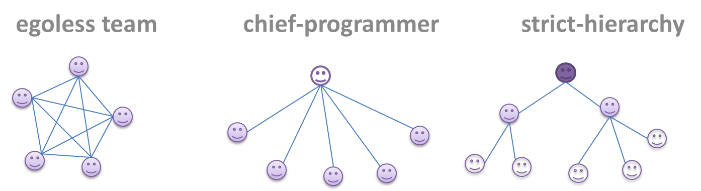
Egoless team
In this structure, every team member is equal in terms of responsibility and accountability. When any decision is required, consensus must be reached. This team structure is also known as a democratic team structure. This team structure usually finds a good solution to a relatively hard problem as all team members contribute ideas.
However, the democratic nature of the team structure bears a higher risk of falling apart due to the absence of an authority figure to manage the team and resolve conflicts.
Chief programmer team
Frederick Brooks proposed that software engineers learn from the medical surgical team in an operating room. In such a team, there is always a chief surgeon, assisted by experts in other areas. Similarly, in a chief programmer team structure, there is a single authoritative figure, the chief programmer. Major decisions, e.g., system architecture, are made solely by him/her and obeyed by all other team members. The chief programmer directs and coordinates the effort of other team members. When necessary, the chief will be assisted by domain specialists e.g., business specialists, database experts, network technology experts, etc. This allows individual group members to concentrate solely on the areas in which they have sound knowledge and expertise.
The success of such a team structure relies heavily on the chief programmer. Not only must he/she be a superb technical hand, he/she also needs good managerial skills. Under a suitably qualified leader, such a team structure is known to produce successful work.
Strict hierarchy team
At the opposite extreme of an egoless team, a strict hierarchy team has a strictly defined organization among the team members, reminiscent of the military or a bureaucratic government. Each team member only works on his/her assigned tasks and reports to a single “boss”.
In a large, resource-intensive, complex project, this could be a good team structure to reduce communication overhead.
SDLC Process Models
Introduction
Software development goes through different stages such as requirements, analysis, design, implementation and testing. These stages are collectively known as the software development lifecycle (SDLC). There are several approaches, known as software development lifecycle models (also called software process models), that describe different ways to go through the SDLC. Each process model prescribes a 'roadmap' for the software developers to manage the development effort. The roadmap describes the aims of the development stages, the outcome of each stage, and the workflow i.e., the relationship between stages.
The sequential model, also called the waterfall model, views software development as a linear process, in which the project is seen as progressing through the development stages. The name waterfall stems from how the model is drawn to look like a waterfall (see below).
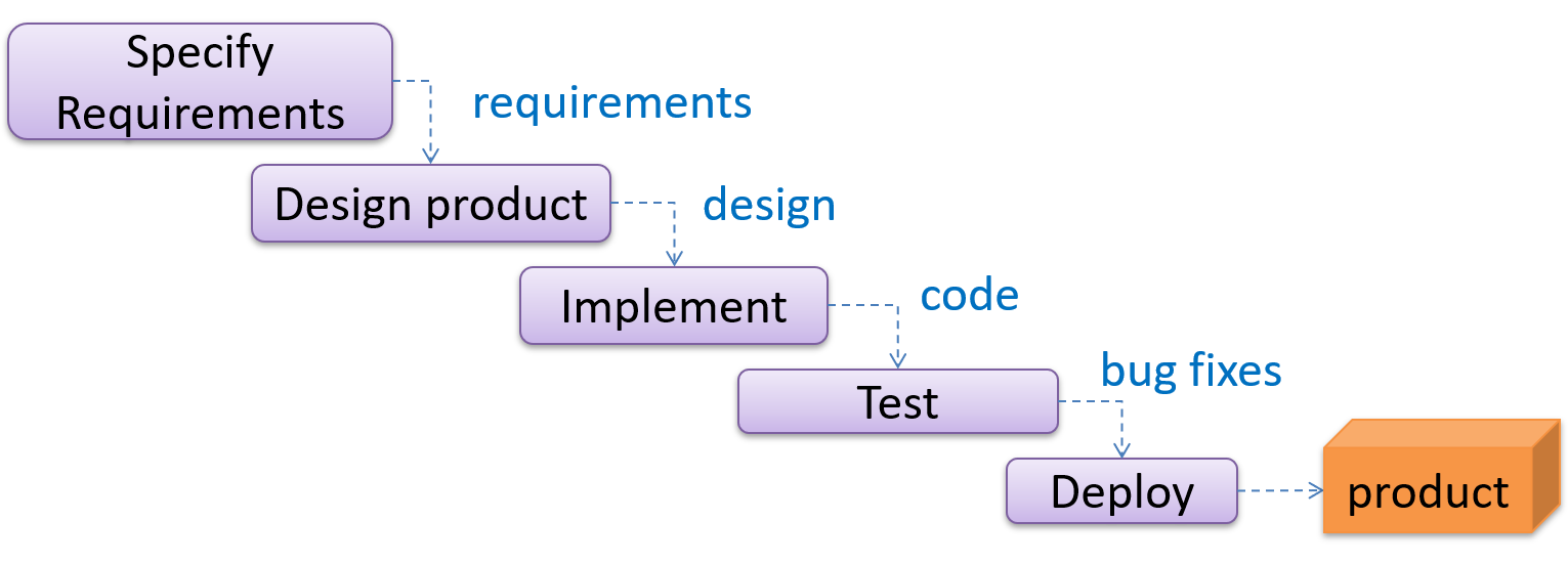
When one stage of the process is completed, it produces some artifacts to be used in the next stage. For example, the requirements stage produces a comprehensive list of requirements, to be used in the design phase.
A strict sequential model project moves only in the forward direction i.e., each stage is completed before starting the next. For example, once the requirements stage is over, there is no provision for revising the requirements later.
This model can work well for a project that produces software to solve a well-understood problem, in which case the requirements can remain stable and the effort can be estimated accurately. Furthermore, as each stage has a well-defined outcome, it is easy to track the progress of the project because one can gauge the project progress by monitoring which stage the project is in.
However, real-world projects often tackle problems that are not well-understood at the beginning, making them unsuitable for this model. For example, target users of a software product may not be able to state their requirements accurately at the start of the project, if they have not used a similar product before.
The iterative model advocates producing the software by going through several iterations. Each of the iterations could potentially go through all the stages of the SDLC, from requirements gathering to deployment.
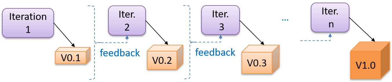
Each iteration produces a new version of the product, building upon the version produced in the previous iteration. Feedback from each iteration is factored into the subsequent iterations. For example, if an implementation task took longer than expected, the effort estimate for a similar tasks in future iterations can be adjusted accordingly. Similarly, if a feature introduced in the current iteration was not well-received by target users, it can be removed or tweaked in the next iteration.
The iterative model can be done in breadth-first or depth-first approach.
- In the breadth-first approach, an iteration evolves all major components and all functionality areas in parallel i.e., most features and most will be updated in each iteration, producing a working product at the end of each iteration.
- In the depth-first approach, an iteration focuses on fleshing out only some components or some functionality area. Accordingly, early depth-first iterations might not produce a working product.
Taking a Minesweeper game as an example,
- breadth-first iterations will deliver a fully playable version early. These early versions may have primitive functionality, for example, a rudimentary text based UI, fixed board size, limited minefield layouts, etc. These functionalities (and corresponding components) will then be improved in later releases.
- an early depth-first iteration could deliver the full user interface (UI) but with no game logic at all. Alternatively, an early iteration could focus on just the logic for generating initial layouts of the minefield. Neither will be a playable version of the game but both can be used to collect early feedback (about the UI, and the initial minefield layouts, respectively) which can then be used to guide later iterations.
A project can be done as a mixture of breadth-first and depth-first iterations i.e., an iteration can contain some breadth-first work as well as some depth-first work, or, some iterations can be breadth-first while others are depth-first.
In 2001, a group of prominent software engineering practitioners met and brainstormed for an alternative to documentation-driven, heavyweight software development processes that were used in most large projects at the time. This resulted in something called the agile manifesto (a vision statement of what they were looking to do).
You are uncovering better ways of developing software by doing it and helping others do it.
Through this work you have come to value:
- Individuals and interactions over processes and tools
- Working software over comprehensive documentation
- Customer collaboration over contract negotiation
- Responding to change over following a plan
That is, while there is value in the items on the right, you value the items on the left more.
-- Extract from the Agile Manifesto
Subsequently, some of the signatories of the manifesto went on to create process models that try to follow it. These processes are collectively called agile processes. Some of the key features of agile approaches are:
- Requirements are prioritized based on the needs of the user, are clarified regularly (at times almost on a daily basis) with the entire project team, and are factored into the development schedule as appropriate.
- Instead of doing a very elaborate and detailed design and a project plan for the whole project, the team works based on a rough project plan and a high level design that evolves as the project goes on.
- There is a strong emphasis on complete transparency and responsibility sharing among the team members. The team is responsible together for the delivery of the product. Team members are accountable, and regularly and openly share progress with each other and with the user.
There are a number of agile processes in the development world today. eXtreme Programming (XP) and Scrum are two of the well-known ones.
Example Process Models
The following description was adapted from the XP home page, emphasis added:
Extreme Programming (XP) stresses customer satisfaction. Instead of delivering everything you could possibly want on some date far in the future, this process delivers the software you need as you need it.
XP aims to empower developers to confidently respond to changing customer requirements, even late in the lifecycle.
XP emphasizes teamwork. Managers, customers, and developers are all equal partners in a collaborative team. XP implements a simple, yet effective environment enabling teams to become highly productive. The team self-organizes around the problem to solve it as efficiently as possible.
XP aims to improve a software project in five essential ways: communication, simplicity, feedback, respect, and courage. Extreme Programmers constantly communicate with their customers and fellow programmers. They keep their design simple and clean. They get feedback by testing their software starting on day one. Every small success deepens their respect for the unique contributions of each and every team member. With this foundation, Extreme Programmers are able to courageously respond to changing requirements and technology.
XP has a set of simple rules. XP is a lot like a jig saw puzzle with many small pieces. Individually the pieces make no sense, but when combined together a complete picture can be seen. This flow chart shows how Extreme Programming's rules work together.
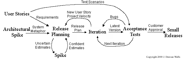
Pair programming, CRC cards, project velocity, and standup meetings are some interesting topics related to XP. Refer to www.extremeprogramming.org to find out more about XP.
This description of Scrum was adapted from Wikipedia [retrieved on 18/10/2011], emphasis added:
Scrum is a process skeleton that contains sets of practices and predefined roles. The main roles in Scrum are:
- The Scrum Master, who maintains the processes (typically in lieu of a project manager)
- The Product Owner, who represents the stakeholders and the business
- The Team, a cross-functional group who do the actual analysis, design, implementation, testing, etc.
A Scrum project is divided into iterations called Sprints. A sprint is the basic unit of development in Scrum. Sprints tend to last between one week and one month, and are a timeboxed (i.e., restricted to a specific duration) effort of a constant length.
Each sprint is preceded by a planning meeting, where the tasks for the sprint are identified and an estimated commitment for the sprint goal is made, and followed by a review or retrospective meeting, where the progress is reviewed and lessons for the next sprint are identified.
During each sprint, the team creates a potentially deliverable product increment (for example, working and tested software). The set of features that go into a sprint come from the product backlog, which is a prioritized set of high level requirements of work to be done. Which backlog items go into the sprint is determined during the sprint planning meeting. During this meeting, the Product Owner informs the team of the items in the product backlog that he or she wants completed. The team then determines how much of this they can commit to complete during the next sprint, and records this in the sprint backlog. During a sprint, no one is allowed to change the sprint backlog, which means that the requirements are frozen for that sprint. Development is timeboxed such that the sprint must end on time; if requirements are not completed for any reason they are left out and returned to the product backlog. After a sprint is completed, the team demonstrates the use of the software.
Scrum enables the creation of self-organizing teams by encouraging co-location of all team members, and verbal communication between all team members and disciplines in the project.
A key principle of Scrum is its recognition that during a project the customers can change their minds about what they want and need (often called requirements churn), and that unpredicted challenges cannot be easily addressed in a traditional predictive or planned manner. As such, Scrum adopts an empirical approach—accepting that the problem cannot be fully understood or defined, focusing instead on maximizing the team’s ability to deliver quickly and respond to emerging requirements.
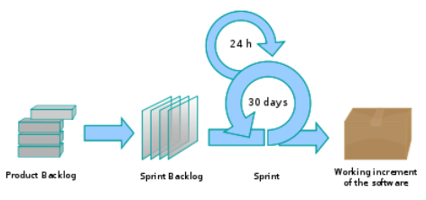
Daily Scrum is another key scrum practice. The description below was adapted from https://www.mountaingoatsoftware.com (emphasis added):
In Scrum, on each day of a sprint, the team holds a daily scrum meeting called the "daily scrum.” Meetings are typically held in the same location and at the same time each day. Ideally, a daily scrum meeting is held in the morning, as it helps set the context for the coming day's work. These scrum meetings are strictly time-boxed to 15 minutes. This keeps the discussion brisk but relevant.
...
During the daily scrum, each team member answers the following three questions:
- What did you do yesterday?
- What will you do today?
- Are there any impediments in your way?
...
The daily scrum meeting is not used as a problem-solving or issue resolution meeting. Issues that are raised are taken offline and usually dealt with by the relevant subgroup immediately after the meeting.
The unified process is developed by the Three Amigos - Ivar Jacobson, Grady Booch and James Rumbaugh (the creators of UML).
The unified process consists of four phases: inception, elaboration, construction and transition. The main purpose of each phase can be summarized as follows:
| Phase | Activities | Typical Artifacts |
|---|---|---|
| Inception |
|
|
| Elaboration |
|
|
| Construction |
|
|
| Transition |
|
|
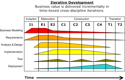
Given above is a visualization of a project done using the Unified process (source: Wikipedia). As the diagram shows, a phase can consist of several iterations. Each vertical column (labeled “I1” “E1”, “E2”, “C1”, etc.) represents a single iteration. Each of the iterations consists of a set of ‘workflows’ such as ‘Business modeling’, ‘Requirements’, ‘Analysis & Design’, etc. The shaded region indicates the amount of resources and effort spent on a particular workflow in a particular iteration.
Unified process is a flexible and customizable process model framework rather than a single fixed process. For example, the number of iterations in each phase, definition of workflows, and the intensity of a given workflow in a given iteration can be adjusted according to the nature of the project. Take the Construction Phase: to develop a simple system, one or two iterations would be sufficient. For a more complicated system, multiple iterations will be more helpful. Therefore, the diagram above simply records a particular application of the UP rather than prescribe how the UP is to be applied. However, this record can be refined and reused for similar future projects.
More
CMMI (Capability Maturity Model Integration) is a process improvement approach defined by Software Engineering Institute at Carnegie Melon University. CMMI provides organizations with the essential elements of effective processes, which will improve their performance. -- adapted from http://www.sei.cmu.edu/cmmi/
CMMI defines five maturity levels for a process and provides criteria to determine if the process of an organization is at a certain maturity level. The diagram below [taken from Wikipedia] gives an overview of the five levels.
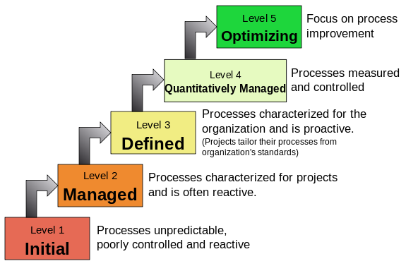
SECTION: PRINCIPLES
Principles
Single responsibility principle (SRP): A class should have one, and only one, reason to change. -- Robert C. Martin
If a class has only one responsibility, it needs to change only when there is a change to that responsibility.
Consider a TextUi class that does parsing of the user commands as well as interacting with the user. That class needs to change when the formatting of the UI changes as well as when the syntax of the user command changes. Hence, such a class does not follow the SRP.
Gather together the things that change for the same reasons. Separate those things that change for different reasons. ―- Agile Software Development, Principles, Patterns, and Practices by Robert C. Martin
Interface segregation principle (ISP): No client should be forced to depend on methods it does not use.
The Payroll class should not depend on the AdminStaff class because it does not use the arrangeMeeting() method. Instead, it should depend on the SalariedStaff interface.
public class Payroll {
// violates ISP
private void adjustSalaries(AdminStaff adminStaff) {
// ...
}
}
public class Payroll {
// does not violate ISP
private void adjustSalaries(SalariedStaff staff) {
// ...
}
}
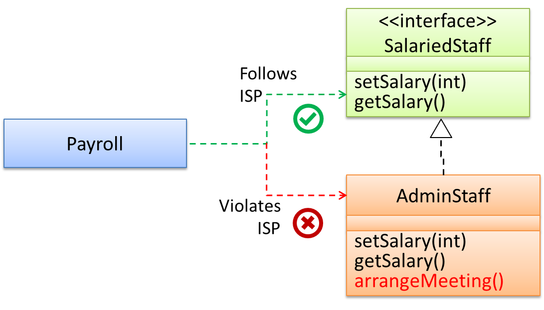
Liskov substitution principle (LSP): Derived classes must be substitutable for their base classes. -- proposed by Barbara Liskov
LSP sounds the same as substitutability but it goes beyond substitutability; LSP implies that a subclass should not be more restrictive than the behavior specified by the superclass. As you know, Java has language support for substitutability. However, if LSP is not followed, substituting a subclass object for a superclass object can break the functionality of the code.
Suppose the Payroll class depends on the adjustMySalary(int percent) method of the Staff class. Furthermore, the Staff class states that the adjustMySalary method will work for all positive percent values. Both the Admin and Academic classes override the adjustMySalary method.
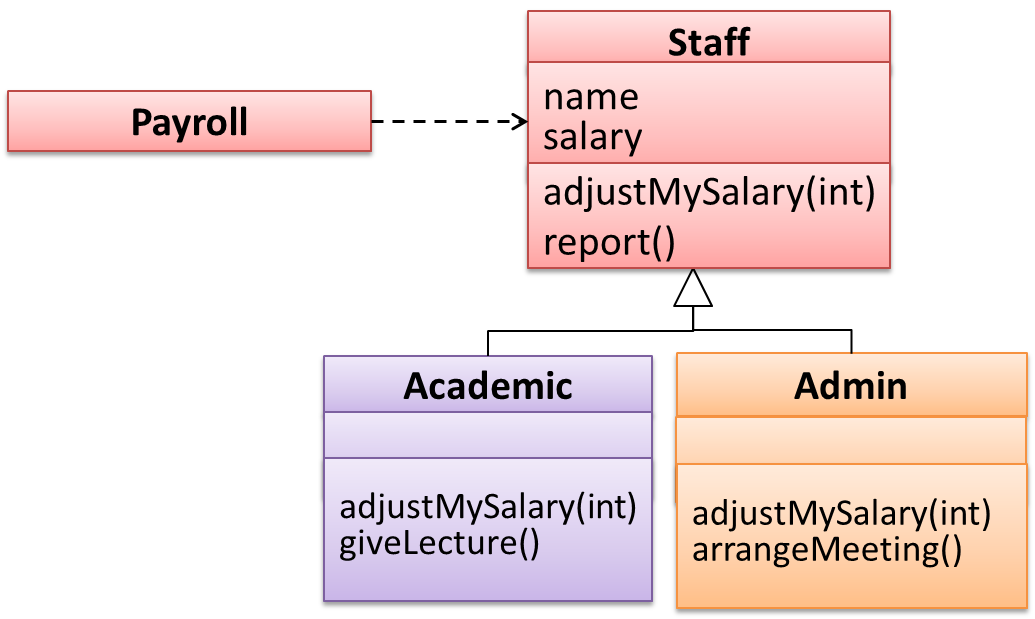
Now consider the following:
- The
Admin#adjustMySalarymethod works for both negative and positive percent values. - The
Academic#adjustMySalarymethod works for percent values1..100only.
In the above scenario,
- The
Adminclass follows LSP because it fulfillsPayroll’s expectation ofStaffobjects (i.e., it works for all positive values). SubstitutingAdminobjects forStaffobjects will not break thePayrollclass functionality. - The
Academicclass violates LSP because it will not work for percent values over100as expected by thePayrollclass. SubstitutingAcademicobjects forStaffobjects can potentially break thePayrollclass functionality.
Dependency inversion principle (DIP):
- High-level modules should not depend on low-level modules. Both should depend on abstractions.
- Abstractions should not depend on details. Details should depend on abstractions.
Example:
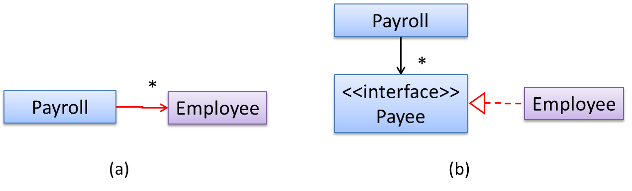
In design (a), the higher level class Payroll depends on the lower level class Employee, which is a violation of DIP. In design (b), both Payroll and Employee depend on the Payee interface (note that inheritance is a dependency).
Design (b) is more flexible (and less coupled) because now the Payroll class need not change when the Employee class changes.
The Open-Closed Principle aims to make a code entity easy to adapt and reuse without needing to modify the code entity itself.
Open-closed principle (OCP): A module should be open for extension but closed for modification. That is, modules should be written so that they can be extended, without requiring them to be modified. -- proposed by Bertrand Meyer
In object-oriented programming, OCP can be achieved in various ways. This often requires separating the specification (i.e., interface) of a module from its implementation.
In the design given below, the behavior of the CommandQueue class can be altered by adding more concrete Command subclasses. For example, by including a Delete class alongside List, Sort, and Reset, the CommandQueue can now perform delete commands without modifying its code at all. That is, its behavior was extended without having to modify its code. Hence, it is open to extensions, but closed to modification.
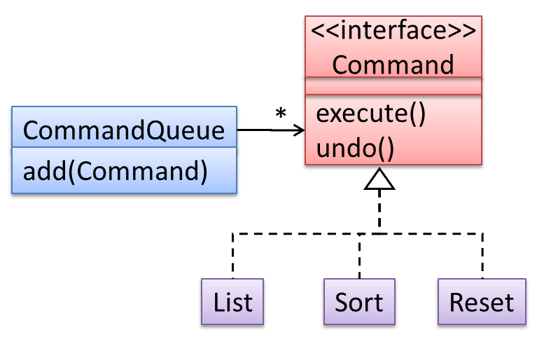
The behavior of a Java generic class can be altered by passing it a different class as a parameter. In the code below, the ArrayList class behaves as a container of Students in one instance and as a container of Admin objects in the other instance, without having to change its code. That is, the behavior of the ArrayList class is extended without modifying its code.
ArrayList students = new ArrayList<Student>();
ArrayList admins = new ArrayList<Admin>();
The five OOP principles given below are known as SOLID Principles (an acronym made up of the first letter of each principle):
Separation of concerns principle (SoC): To achieve better modularity, separate the code into distinct sections, such that each section addresses a separate concern. -- Proposed by Edsger W. Dijkstra
A concern in this context is a set of information that affects the code of a computer program.
Examples for concerns:
- A specific feature, such as the code related to the
add employeefeature - A specific aspect, such as the code related to
persistenceorsecurity - A specific entity, such as the code related to the
Employeeentity
Applying reduces functional overlaps among code sections and also limits the ripple effect when changes are introduced to a specific part of the system.
If the code related to persistence is separated from the code related to security, a change to how the data are persisted will not need changes to how the security is implemented.
This principle can be applied at the class level, as well as at higher levels.
The n-tier architecture utilizes this principle. Each layer in the architecture has a well-defined functionality that has no functional overlap with each other.
This principle should lead to higher cohesion and lower coupling.
Law of Demeter (LoD):
- An object should have limited knowledge of another object.
- An object should only interact with objects that are closely related to it.
Also known as
- Don’t talk to strangers.
- Principle of least knowledge
More concretely, a method m of an object O should invoke only the methods of the following kinds of objects:
- The object
Oitself - Objects passed as parameters of
m - Objects created/instantiated in
m(directly or indirectly) - Objects from the
The following code fragment violates LoD due to the following reason: while b is a ‘friend’ of foo (because it receives it as a parameter), g is a ‘friend of a friend’ (which should be considered a ‘stranger’), and g.doSomething() is analogous to ‘talking to a stranger’.
void foo(Bar b) {
Goo g = b.getGoo();
g.doSomething();
}
LoD aims to prevent objects from navigating the internal structures of other objects.
An analogy for LoD can be drawn from Facebook. If Facebook followed LoD, you would not be allowed to see posts of friends of friends, unless they are your friends as well. If Jake is your friend and Adam is Jake’s friend, you should not be allowed to see Adam’s posts unless Adam is a friend of yours as well.
Brooks' law: Adding people to a late project will make it later. -- Fred Brooks (author of The Mythical Man-Month)
Explanation: The additional communication overhead will outweigh the benefit of adding extra manpower, especially if done near a deadline.
YAGNI (You Aren't Gonna Need It!) Principle: Do not add code simply because ‘you might need it in the future’.
The principle says that some capability you presume your software needs in the future should not be built now because chances are "you aren't gonna need it". The rationale is that you do not have perfect information about the future and therefore some of the extra work you do to fulfill a potential future need might go to waste when some of your predictions fail to materialize.
DRY (Don't Repeat Yourself) principle: Every piece of knowledge must have a single, unambiguous, authoritative representation within a system. -- The Pragmatic Programmer, by Andy Hunt and Dave Thomas
This principle guards against the duplication of information.
A functionality being implemented twice is a violation of the DRY principle even if the two implementations are different.
The value of a system-wide timeout being defined in multiple places is a violation of DRY.
SECTION: SUPPLEMENTARY
C++ to Java
This book chapter assumes you are familiar with basic C++ programming. It provides a crash course to help you migrate from C++ to Java.
This chapter borrows heavily from the excellent book ThinkJava by Allen Downey and Chris Mayfield. As required by the terms of reuse of that book, this chapter is released under the Creative Commons Attribution-NonCommercial-ShareAlike 3.0 Unported License and not under the MIT license as the rest of this book.
Some conventions used in this chapter:
icon marks the description of an aspect of Java that works mostly similar to C++
icon marks the description of an aspect of Java that is distinctly different from C++
Other resources used:
- C++ and Java Syntax Differences Cheat Sheet by Alex Allain
- Java Tutorial provided by Oracle. Extracts from this resource are marked as -- Java Tutorial
The Java World
Java was conceived by James Gosling and his team at Sun Microsystems in 1991.
Java is directly related to both C and C++. Java inherits its syntax from C. Its object model is adapted from C++. --Java: A Beginner’s Guide, by Oracle
Fun fact: The language was initially called Oak after an oak tree that stood outside Gosling's office. Later the project went by the name Green and was finally renamed Java, from Java coffee. --Wikipedia
Oracle became the owner of Java in 2010, when it acquired Sun Microsystems.
Java has remained the most popular language in the world for several years now (as at July 2018), according to the TIOBE index.
Java is both and . Instead of translating programs directly into machine language, the Java compiler generates byte code. Byte code is portable, so it is possible to compile a Java program on one machine, transfer the byte code to another machine, and run the byte code on the other machine. That’s why Java is considered a platform independent technology, aka WORA (Write Once Run Anywhere). The interpreter that runs byte code is called a “Java Virtual Machine” (JVM).
Java technology is both a programming language and a platform. The Java programming language is a high-level object-oriented language that has a particular syntax and style. A Java platform is a particular environment in which Java programming language applications run. --Oracle
According to the Official Java documentation, there are four platforms of the Java programming language:
Java Platform, Standard Edition (Java SE): Contains the core functionality of the Java programming language.
Java Platform, Enterprise Edition (Java EE): For developing and running large-scale enterprise applications. Built on top of Java SE.
Java Platform, Micro Edition (Java ME): For Java programming language applications meant for small devices, like mobile phones. A subset of Java SE.
JavaFX: For creating applications with graphical user interfaces. Can work with the other three above.
This book chapter uses the Java SE edition unless stated otherwise.
Getting Started
To run Java programs, you only need to have a recent version of the Java Runtime Environment (JRE) installed in your device.
If you want to develop applications for Java, download and install a recent version of the Java Development Kit (JDK), which includes the JRE as well as additional resources needed to develop Java applications.
In Java, the HelloWorld program looks like this:
public class HelloWorld {
public static void main(String[] args) {
// generate some simple output
System.out.println("Hello, World!");
}
}
For reference, the equivalent C++ code is given below:
#include <iostream>
using namespace std;
int main() {
// generate some simple output
cout << "Hello, World!";
return 0;
}
This HelloWorld Java program defines one method named main: public static void main(String[] args)
System.out.println() displays a given text on the screen.
Some similarities:
- Java programs consists of statements, grouped , which are then grouped into classes.
- Java is “case-sensitive”, which means
SYSTEMis different fromSystem. publicis an access modifier that indicates the method is accessible from outside this class. Similarly,privateaccess modifier indicates that a method/attribute is not accessible outside the class.staticindicates this method is defined as a class-level member. Do not worry if you don’t know what that means. It will be explained later.voidindicates that the method does not return anything.- The name and format of the
mainmethod is special as it is the method that Java executes when you run a Java program. - A class is a collection of methods. This program defines a class named
HelloWorld. - Java uses squiggly braces (
{and}) to group things together. - The line starting with
//is a comment. You can use//for single line comments and/* ... */for multi-line comments in Java code.
Some differences:
- Java use the term method instead of function. In particular, Java doesn’t have stand-alone functions. Every method should belong to a class. The
mainmethod will not work unless it is inside theHelloWorldclass. - A Java class definition does not end with a semicolon, but most Java statements do.
- In most cases (i.e., there are exceptions), the name of the class has to match the name of the file it is in, so this class has to be in a file named
HelloWorld.java. - There is no need for the HelloWorld code to have something like
#include <iostream>. The library files needed by the HelloWorld code is available by default without having to "include" them explicitly. - There is no need to
return 0at the end of the main method to indicate the execution was successful. It is considered as a successful execution unless an error is signalled specifically.
To compile the HelloWorld program, open a command console, navigate to the folder containing the file, and run the following command.
>_ javac HelloWorld.java
If the compilation is successful, you should see a file HelloWorld.class. That file contains the byte code for your program. If the compilation is unsuccessful, you will be notified of the compile-time errors.
Notes:
javacis the java compiler that you get when you install the JDK.- For the above command to work, your console program should be able to find the javac executable (e.g., In Windows, the location of the
javac.exeshould be in thePATHsystem variable).
This page shows how to set PATH in different OS'es.
To run the HelloWorld program, in a command console, run the following command from the folder containing HelloWorld.class file.
>_ java HelloWorld
Notes:
javain the command above refers to the Java interpreter installed on your computer.- Similar to
javac, your console should be able to find the java executable.
When you run a Java program, you can encounter a . These errors are also called "exceptions" because they usually indicate that something exceptional (and bad) has happened. When a run-time error occurs, the interpreter displays an error message that explains what happened and where.
For example, modify the HelloWorld code to include the following line, compile it again, and run it.
System.out.println(5/0);
You should get a message like this:
Exception in thread "main" java.lang.ArithmeticException: / by zero
at Hello.main(Hello.java:5)
Integrated Development Environments (IDEs) can automate the intermediate step of compiling. They usually have a Run button which compiles the code first and then runs it.
Example IDEs:
- IntelliJ IDEA
- Eclipse
- NetBeans
Data Types
Java has a number of primitive data types, as given below:
byte: an integer in the range -128 to 127 (inclusive).short: an integer in the range -32,768 to 32,767 (inclusive).int: an integer in the range -231 to 231-1.long: An integer in the range -263 to 263-1.float: a single-precision 32-bit IEEE 754 floating point. This data type should never be used for precise values, such as currency. For that, you will need to use the java.math.BigDecimal class instead.double: a double-precision 64-bit IEEE 754 floating point. For decimal values, this data type is generally the default choice. This data type should never be used for precise values, such as currency.boolean: has only two possible values:trueandfalse.char: The char data type is a single 16-bit Unicode character. It has a minimum value of'\u0000'(or0) and a maximum value of'\uffff'(or65,535inclusive).
The String type (a peek)
Java has a built-in type called String to represent strings. While String is not a primitive type, strings are used often. String values are demarcated by enclosing in a pair of double quotes (e.g., "Hello"). You can use the + operator to concatenate strings (e.g., "Hello " + "!").
You’ll learn more about strings in a later section.
Java is a statically-typed language in that variables have a fixed type. Here are some examples of declaring variables and assigning values to them.
int x;
x = 5;
int hour = 11;
boolean isCorrect = true;
char capitalC = 'C';
byte b = 100;
short s = 10000;
int i = 100000;
You can use any name starting with a letter, underscore, or $ as a variable name but you cannot use Java keywords as variables names.
You can display the value of a variable using System.out.print or System.out.println (the latter goes to the next line after printing). To output multiple values on the same line, it’s common to use several print statements followed by println at the end.
int hour = 11;
int minute = 59;
System.out.print("The current time is ");
System.out.print(hour);
System.out.print(":");
System.out.print(minute);
System.out.println("."); //use println here to complete the line
System.out.println("done");
The current time is 11:59.
done
Use the keyword final to indicate that the variable value, once assigned, should not be allowed to change later i.e., act like a ‘constant’. By convention, names for constants are all uppercase, with the underscore character (_) between words.
final double CM_PER_INCH = 2.54;
Java supports the usual arithmetic operators, given below.
| Operator | Description | Examples |
|---|---|---|
+ | Additive operator | 2 + 3 5 |
- | Subtraction operator | 4 - 1 3 |
* | Multiplication operator | 2 * 3 6 |
/ | Division operator | 5 / 2 2 but 5.0 / 2 2.5 |
% | Remainder operator | 5 % 2 1 |
The following program uses some operators as part of an expression hour * 60 + minute:
int hour = 11;
int minute = 59;
System.out.print("Number of minutes since midnight: ");
System.out.println(hour * 60 + minute);
Number of minutes since midnight: 719
When an expression has multiple operators, normal operator precedence rules apply. Furthermore, you can use parentheses to specify a precise precedence.
Examples:
4 * 5 - 119(*has higher precedence than-)4 * (5 - 1)16(parentheses()have higher precedence than*)
Java does not allow .
The unary operators require only one operand; they perform various operations such as incrementing/decrementing a value by one, negating an expression, or inverting the value of a boolean.-- Java Tutorial
| Operator | Description -- Java Tutorial | example |
|---|---|---|
+ | Unary plus operator; indicates positive value (numbers are positive without this, however) | x = 5; y = +x y is 5 |
- | Unary minus operator; negates an expression | x = 5; y = -x y is -5 |
++ | Increment operator; increments a value by 1 | i = 5; i++ i is 6 |
-- | Decrement operator; decrements a value by 1 | i = 5; i-- i is 4 |
! | Logical complement operator; inverts the value of a boolean | foo = true; bar = !foo bar is false |
Relational operators are used to check conditions like whether two values are equal, or whether one is greater than the other. The following expressions show how they are used:
| Operator | Description | example true | example false |
|---|---|---|---|
x == y | x is equal to y | 5 == 5 | 5 == 6 |
x != y | x is not equal to y | 5 != 6 | 5 != 5 |
x > y | x is greater than y | 7 > 6 | 5 > 6 |
x < y | x is less than y | 5 < 6 | 7 < 6 |
x >= y | x is greater than or equal to y | 5 >= 5 | 4 >= 5 |
x <= y | x is less than or equal to y | 4 <= 5 | 6 <= 5 |
The result of a relational operator is a boolean value.
Java has three conditional operators that are used to operate on boolean values.
| Operator | Description | example true | example false |
|---|---|---|---|
&& | and | true && true true | true && false false |
|| | or | true || false true | false || false false |
! | not | not false | not true |
Arrays are indicated using square brackets ([]). To create the array itself, you have to use the new operator. Here are some example array declarations:
int[] counts;
counts = new int[4]; // create an int array of size 4
int size = 5;
double[] values;
values = new double[size]; //use a variable for the size
double[] prices = new double[size]; // declare and create at the same time
Alternatively, you can use the shortcut syntax to create and initialize an array:int[] values = {1, 2, 3, 4, 5, 6}; int[] anArray = { 100, 200, 300, 400, 500, 600, 700, 800, 900, 1000 };-- Java Tutorial
The [] operator selects elements from an array. Array elements .
int[] counts = new int[4];
System.out.println("The first element is " + counts[0]);
counts[0] = 7; // set the element at index 0 to be 7
counts[1] = counts[0] * 2;
counts[2]++; // increment value at index 2
A Java array is aware of its size. A Java array prevents a programmer from indexing the array out of bounds. If the index is negative or not present in the array, the result is an error named ArrayIndexOutOfBoundsException.
int[] scores = new int[4];
System.out.println(scores.length) // prints 4
scores[5] = 0; // causes an exception
4
Exception in thread "main" java.lang.ArrayIndexOutOfBoundsException: 5
at Main.main(Main.java:6)
It is also possible to create arrays of more than one dimension:
String[][] names = { {"Mr. ", "Mrs. ", "Ms. "}, {"Smith", "Jones"} }; System.out.println(names[0][0] + names[1][0]); // Mr. Smith System.out.println(names[0][2] + names[1][1]); // Ms. Jones-- Java Tutorial
Passing arguments to a program
The args parameter of the main method is an array of Strings containing command line arguments supplied (if any) when running the program.
public class Foo{
public static void main(String[] args) {
System.out.println(args[0]);
}
}
You can run this program (after compiling it first) from the command line by typing:
>_ java Foo abc
abc
Control Flow
if-else statements
Java supports the usual forms of if statements:
if (x > 0) {
System.out.println("x is positive");
}
if (x % 2 == 0) {
System.out.println("x is even");
} else {
System.out.println("x is odd");
}
if (x > 0) {
System.out.println("x is positive");
} else if (x < 0) {
System.out.println("x is negative");
} else {
System.out.println("x is zero");
}
if (x == 0) {
System.out.println("x is zero");
} else {
if (x > 0) {
System.out.println("x is positive");
} else {
System.out.println("x is negative");
}
}
The braces are optional (but recommended) for branches that have only one statement. So we could have written the previous example this way ( Bad):
if (x % 2 == 0)
System.out.println("x is even");
else
System.out.println("x is odd");
switch statements
The switch statement can have a number of possible execution paths. A switch works with the byte, short, char, and int primitive data types. It also works with enums, String.
Here is an example (adapted from -- Java Tutorial):
public class SwitchDemo {
public static void main(String[] args) {
int month = 8;
String monthString;
switch (month) {
case 1: monthString = "January";
break;
case 2: monthString = "February";
break;
case 3: monthString = "March";
break;
case 4: monthString = "April";
break;
case 5: monthString = "May";
break;
case 6: monthString = "June";
break;
case 7: monthString = "July";
break;
case 8: monthString = "August";
break;
case 9: monthString = "September";
break;
case 10: monthString = "October";
break;
case 11: monthString = "November";
break;
case 12: monthString = "December";
break;
default: monthString = "Invalid month";
break;
}
System.out.println(monthString);
}
}
August
Java has while and for constructs for looping.
while loops
Here is an example while loop:
public static void countdown(int n) {
while (n > 0) {
System.out.println(n);
n = n - 1;
}
System.out.println("Blastoff!");
}
for loops
for loops have the form:
for (initializer; condition; update) {
statement(s);
}
Here is an example:
public static void printTable(int rows) {
for (int i = 1; i <= rows; i = i + 1) {
printRow(i, rows);
}
}
do-while loops
The while and for statements are pretest loops; that is, they test the condition first and at the beginning of each pass through the loop. Java also provides a posttest loop: the do-while statement. This type of loop is useful when you need to run the body of the loop at least once.
Here is an example (from -- Java Tutorial):
class DoWhileDemo {
public static void main(String[] args){
int count = 1;
do {
System.out.println("Count is: " + count);
count++;
} while (count < 11);
}
}
break and continue
A break statement exits the current loop.
Here is an example (from -- Java Tutorial):
class Main {
public static void main(String[] args) {
int[] numbers = new int[] { 1, 2, 3, 0, 4, 5, 0 };
for (int i = 0; i < numbers.length; i++) {
if (numbers[i] == 0) {
break;
}
System.out.print(numbers[i]);
}
}
}
123
[Try the above code on Repl.it]
A continue statement skips the remainder of the current iteration and moves to the next iteration of the loop.
Here is an example (from -- Java Tutorial):
public static void main(String[] args) {
int[] numbers = new int[] { 1, 2, 3, 0, 4, 5, 0 };
for (int i = 0; i < numbers.length; i++) {
if (numbers[i] == 0) {
continue;
}
System.out.print(numbers[i]);
}
}
12345
Enhanced for loops
Since traversing arrays is so common, Java provides an alternative for-loop syntax that makes the code more compact. For example, consider a for loop that displays the elements of an array on separate lines:
for (int i = 0; i < values.length; i++) {
int value = values[i];
System.out.println(value);
}
We could rewrite the loop like this:
for (int value : values) {
System.out.println(value);
}
This statement is called an enhanced for loop. You can read it as, “for each value in values”.
Notice how the single line for (int value : values) replaces the first two lines of the standard for loop.
Defining methods
Here’s an example of adding more methods to a class:
public class PrintTwice {
public static void printTwice(String s) {
System.out.println(s);
System.out.println(s);
}
public static void main(String[] args) {
String sentence = “Polly likes crackers”
printTwice(sentence);
}
}
Polly likes crackers
Polly likes crackers
By convention, method names should be named in the camelCase format.
Similar to the main method, the printTwice method is public (i.e., it can be invoked from other classes) static and void.
Parameters
A method can specify parameters. The printTwice method above specifies a parameter of String type. The main method passes the argument "Polly likes crackers" to that parameter.
The value provided as an argument must have the same type as the parameter. Sometimes Java can convert an argument from one type to another automatically. For example, if the method requires a double, you can invoke it with an int argument 5 and Java will automatically convert the argument to the equivalent value of type double 5.0.
Because a variable declared inside a method only exists inside that method, such variables are called local variables. That applies to parameters of a method too. For example, In the code above, s cannot be used inside main because it is a parameter of the printTwice method and can only be used inside that method. If you try to use s inside main, you’ll get a compiler error. Similarly, inside printTwice there is no such thing as sentence. That variable belongs to main.
return statements
The return statement allows you to terminate a method before you reach the end of it:
public static void printLogarithm(double x) {
if (x <= 0.0) {
System.out.println("Error: x must be positive.");
return;
}
double result = Math.log(x);
System.out.println("The log of x is " + result);
}
It can be used to return a value from a method too:
public class AreaCalculator{
public static double calculateArea(double radius) {
double result = 3.14 * radius * radius;
return result;
}
public static void main(String[] args) {
double area = calculateArea(12.5);
System.out.println(area);
}
}
Overloading
Java methods can be overloaded. If two methods do the same thing, it is natural to give them the same name. Having more than one method with the same name is called overloading, and it is legal in Java as long as each version has a different method signature (the signature of the method is the method name and ordered list of parameter types) . For example, the following overloading of the method calculateArea is allowed because the method signatures are different (i.e., calculateArea(double) vs calculateArea(double, double)).
public static double calculateArea(double radius) {
//...
}
public static double calculateArea(double height, double width) {
//...
}
Recursion
Methods can be recursive. Here is an example in which the nLines method calls itself recursively:
public static void nLines(int n) {
if (n > 0) {
System.out.println();
nLines(n - 1);
}
}
Java Objects
Java is an "object-oriented" language, which means that it uses objects to represent data and provide methods related to them. Object types are called classes e.g., you can use String objects in Java and those objects belong to the String class.
importing
Java comes with many inbuilt classes which are organized into packages. Here are some examples:
| package | Some example classes in the package |
|---|---|
java.lang | String, Math, System |
Before using a class in your code, you need to import the class. import statements appear at the top of the code.
This example imports the java.awt.Point class (i.e., the Point class in the java.awt package) -- which can be used to represent the coordinates of a location in a Cartesian plane -- and use it in the main method.
import java.awt.Point;
public class Main{
public static void main(String[] args) {
Point spot = new Point(3, 4);
int x = spot.x;
System.out.println(x);
}
}
You might wonder why we can use the System class without importing it. System belongs to the java.lang package, which is imported automatically.
new operator
To create a new object, you have to use the new operator
This line shows how to create a new Point object using the new operator:
Point spot = new Point(3, 4);
Variables that belong to an object are called attributes (or fields).
To access an attribute of an object, Java uses dot notation.
The code below uses spot.x which means "go to the object spot refers to, and get the value of the attribute x."
Point spot = new Point(3, 4);
int sum = spot.x * spot.x + spot.y * spot.y;
System.out.println(spot.x + ", " + spot.y + ", " + sum);
3, 4, 25
You can an object by assigning a different value to its attributes.
This example changes the x value of the Point object to 5.
Point spot = new Point(3, 4);
spot.x = 5;
System.out.println(spot.x + ", " + spot.y);
5, 4
Java uses the dot notation to invoke methods on an object too.
This example invokes the translate method on a Point object so that it moves to a different location.
Point spot = new Point(3, 4);
System.out.println(spot.x + ", " + spot.y);
spot.translate(5,5);
System.out.println(spot.x + ", " + spot.y);
3, 4
8, 9
You can pass objects as parameters to a method in the usual way.
The printPoint method below takes a Point object as an argument and displays its attributes in (x,y) format.
public static void printPoint(Point p) {
System.out.println("(" + p.x + ", " + p.y + ")");
}
public static void main(String[] args) {
Point spot = new Point(3, 4);
printPoint(spot);
}
(3, 4)
You can return an object from a method too.
The java.awt package also provides a class called Rectangle. Rectangle objects are similar to points, but they have four attributes: x, y, width, and height. The findCenter method below takes a Rectangle as an argument and returns a Point that corresponds to the center of the rectangle:
public static Point findCenter(Rectangle box) {
int x = box.x + box.width / 2;
int y = box.y + box.height / 2;
return new Point(x, y);
}
The return type of this method is Point. The last line creates a new Point object and returns a reference to it.
null and NullPointerException
null is a special value that means "no object". You can assign null to a variable to indicate that the variable is 'empty' at the moment. However, if you try to use a null value, either by accessing an attribute or invoking a method, Java throws a NullPointerException.
In this example, the variable spot is assigned a null value. As a result, trying to access spot.x attribute or invoking the spot.translate method results in a NullPointerException.
Point spot = null;
int x = spot.x; // NullPointerException
spot.translate(50, 50); // NullPointerException
On the other hand, it is legal to return null from a method or to pass a null reference as an argument to a method.
Returning null from a method.
public static Point createCopy(Point p) {
if (p == null) {
return null; // return null if p is null
}
// create a new object with same x,y values
return new Point(p.x, p.y);
}
Passing null as the argument.
Point result = createCopy(null);
System.out.println(result);
null
It is possible to have multiple variables that refer to the same object.
Notice how p1 and p2 are aliases for the same object. When the object is changed using the variable p1, the changes are visible via p2 as well (and vice versa), because they both point to the same Point object.
Point p1 = new Point(0,0);
Point p2 = p1;
System.out.println("p1: " + p1.x + ", " + p1.y);
System.out.println("p2: " + p2.x + ", " + p2.y);
p1.x = 1;
p2.y = 2;
System.out.println("p1: " + p1.x + ", " + p1.y);
System.out.println("p2: " + p2.x + ", " + p2.y);
p1: 0, 0
p2: 0, 0
p1: 1, 2
p2: 1, 2
Java does not have explicit pointers (and other related things such as pointer de-referencing and pointer arithmetic). When an object is passed into a method as an argument, the method gains access to the original object. If the method changes the object it received, the changes are retained in the object even after the method has completed.
Note how p3 retains changes done to it by the method swapCoordinates even after the method has completed executing.
public static void swapCoordinates(Point p){
int temp = p.x;
p.x = p.y;
p.y = temp;
}
public static void main(String[] args) {
Point p3 = new Point(2,3);
System.out.println("p3: " + p3.x + ", " + p3.y);
swapCoordinates(p3);
System.out.println("p3: " + p3.x + ", " + p3.y);
}
p3: 2, 3
p3: 3, 2
What happens when no variables refer to an object?
Point spot = new Point(3, 4);
spot = null;
The first line creates a new Point object and makes spot refer to it. The second line changes spot so that instead of referring to the object, it refers to nothing. If there are no references to an object, there is no way to access its attributes or invoke a method on it. From the programmer’s view, it ceases to exist. However, it’s still present in the computer’s memory, taking up space.
In Java, you don’t have to delete objects you create when they are no longer needed. As your program runs, the system automatically looks for stranded objects and reclaims them; then the space can be reused for new objects. This process is called garbage collection. You don’t have to do anything to make garbage collection happen, and in general don’t have to be aware of it. But in high-performance applications, you may notice a slight delay every now and then when Java reclaims space from discarded objects.
Java Classes
As you know,
- Defining a class introduces a new object type.
- Every object belongs to some object type; that is, it is an instance of some class.
- A class definition is like a template for objects: it specifies what attributes the objects have and what methods they have.
- The
newoperator instantiates objects, that is, it creates new instances of a class. - The methods that operate on an object type are defined in the class for that object.
Here's a class called Time, intended to represent a moment in time. It has three attributes and no methods.
public class Time {
private int hour;
private int minute;
private int second;
}
You can give a class any name you like. The Java convention is to use format for class names.
The code is placed in a file whose name matches the class e.g., the Time class should be in a file named Time.java.
When a class is public (e.g., the Time class in the above example) it can be used in other classes. But the that are private (e.g., the hour, minute and second attributes of the Time class) can only be accessed from inside the Time class.
Constructors
The syntax for is similar to that of other methods, except:
- The name of the constructor is the same as the name of the class.
- The keyword
staticis omitted. - Does not return anything. A constructor returns the created object by default.
When you invoke new, Java creates the object and calls your constructor to initialize the instance variables. When the constructor is done, it returns a reference to the new object.
Here is an example constructor for the Time class:
public Time() {
hour = 0;
minute = 0;
second = 0;
}
This constructor does not take any arguments. Each line initializes an instance variable to 0 (which in this example means midnight).
Now you can create Time objects.
Time time = new Time();
Like other methods, constructors can be .
You can add another constructor to the Time class to allow creating Time objects that are initialized to a specific time:
public Time(int h, int m, int s) {
hour = h;
minute = m;
second = s;
}
Here's how you can invoke the new constructor:
Time justBeforeMidnight = new Time(11, 59, 59);
this keyword
The this keyword is a reference variable in Java that refers to the . You can use this the same way you use the name of any other object. For example, you can read and write the instance variables of this, and you can pass this as an argument to other methods. But you do not declare this, and you can’t make an assignment to it.
In the following version of the constructor, the names and types of the parameters are the same as the instance variables (parameters don’t have to use the same names, but that’s a common style). As a result, the parameters shadow (or hide) the instance variables, so the keyword this is necessary to tell them apart.
public Time(int hour, int minute, int second) {
this.hour = hour;
this.minute = minute;
this.second = second;
}
this can be used to refer to a constructor of a class within the same class too.
In this example the constructor Time() uses the this keyword to call its own constructor Time(int, int, int)
public Time() {
this(0, 0, 0); // call the overloaded constructor
}
public Time(int hour, int minute, int second) {
// ...
}
Instance methods
You can add methods to a class which can then be used from the objects of that class. These instance methods do not have the static keyword in their method signature. Instance methods can access attributes of the class.
Here's how you can add a method to the Time class to get the number of seconds passed since midnight.
public int secondsSinceMidnight() {
return hour*60*60 + minute*60 + second;
}
Here's how you can use that method.
Time t = new Time(0, 2, 5);
System.out.println(t.secondsSinceMidnight() + " seconds since midnight!");
As the instance variables of Time are private, you can access them from within the Time class only. To compensate, you can provide methods to access attributes:
public int getHour() {
return hour;
}
public int getMinute() {
return minute;
}
public int getSecond() {
return second;
}
Methods like these are formally called “accessors”, but more commonly referred to as getters. By convention, the method that gets a variable named something is called getSomething.
Similarly, you can provide setter methods to modify attributes of a Time object:
public void setHour(int hour) {
this.hour = hour;
}
public void setMinute(int minute) {
this.minute = minute;
}
public void setSecond(int second) {
this.second = second;
}
The content below is an extract from -- Java Tutorial, with slight adaptations.
When a number of objects are created from the same class blueprint, they each have their own distinct copies of instance variables. In the case of a Bicycle class, the instance variables are gear, and speed. Each Bicycle object has its own values for these variables, stored in different memory locations.
Sometimes, you want to have variables that are common to all objects. This is accomplished with the static modifier. Fields that have the static modifier in their declaration are called static fields or class variables. They are associated with the class, rather than with any object. Every instance of the class shares a class variable, which is in one fixed location in memory. Any object can change the value of a class variable, but class variables can also be manipulated without creating an instance of the class.
Suppose you want to create a number of Bicycle objects and assign each a serial number, beginning with 1 for the first object. This ID number is unique to each object and is therefore an instance variable. At the same time, you need a field to keep track of how many Bicycle objects have been created so that you know what ID to assign to the next one. Such a field is not related to any individual object, but to the class as a whole. For this you need a class variable, numberOfBicycles, as follows:
public class Bicycle {
private int gear;
private int speed;
// an instance variable for the object ID
private int id;
// a class variable for the number of Bicycle
// objects instantiated
private static int numberOfBicycles = 0;
...
}
Class variables are referenced by the class name itself, as in Bicycle.numberOfBicycles This makes it clear that they are class variables.
The Java programming language supports static methods as well as static variables. Static methods, which have the static modifier in their declarations, should be invoked with the class name, without the need for creating an instance of the class, as in ClassName.methodName(args)
The static modifier, in combination with the final modifier, is also used to define constants. The final modifier indicates that the value of this field cannot change. For example, the following variable declaration defines a constant named PI, whose value is an approximation of pi (the ratio of the circumference of a circle to its diameter):
static final double PI = 3.141592653589793;
Here is an example with class-level variables and class-level methods:
public class Bicycle {
private int gear;
private int speed;
private int id;
private static int numberOfBicycles = 0;
public Bicycle(int startSpeed, int startGear) {
gear = startGear;
speed = startSpeed;
numberOfBicycles++;
id = numberOfBicycles;
}
public int getID() {
return id;
}
public static int getNumberOfBicycles() {
return numberOfBicycles;
}
public int getGear(){
return gear;
}
public void setGear(int newValue) {
gear = newValue;
}
public int getSpeed() {
return speed;
}
// ...
}
Explanation of System.out.println(...):
outis a class-level public attribute of theSystemclass.printlnis an instance level method of theoutobject.
Some Useful Classes
Java comes with a rich collection of classes that you can use. They form what is known as the Java API (Application Programming Interface). Each class in the API comes with documentation in a standard format.
String is a built-in Java class that you can use without importing. Given below are some useful String methods:
Find characters of a string
Strings provide a method named charAt, which extracts a character. It returns a char, a primitive type that stores an individual character (as opposed to strings of them).
String fruit = "banana";
char letter = fruit.charAt(0);
The argument 0 means that we want the letter at position 0. Like array indexes, string indexes start at 0, so the character assigned to letter is 'b'.
You can convert a string to an array of characters using the toCharArray method.
char[] fruitChars = fruit.toCharArray()
Change a string to upper/lower case
Strings provide methods, toUpperCase and toLowerCase, that convert from uppercase to lowercase and back.
After these statements run, upperName refers to the string "ALAN TURING" but name still refers to "Alan Turing".
String name = "Alan Turing";
String upperName = name.toUpperCase();
System.out.println(name);
System.out.println(upperName);
Alan Turing
ALAN TURING
Note that a string method cannot change the string object on which the method is invoked, because strings are . For example, when you invoke toUpperCase on a string "abc", you get a new string object "ABC" as the return value rather than the string "abc" being changed to "ABC". As a result, for such string methods that seemingly modify the string but actually return a new string instead e.g., toLowerCase, invoking the method has no effect if you don’t assign the return value to a variable.
String s = "Ada";
s.toUpperCase(); // no effect
s = s.toUpperCase(); // the correct way
Replacing parts of a string
Another useful method is replace, which finds and replaces instances of one string within another.
This example replaces "Computer Science" with "CS".
String text = "Computer Science is fun!";
text = text.replace("Computer Science", "CS");
System.out.println(text);
CS is fun!
Accessing substrings
The substring method returns a new string that copies letters from an existing string, starting at the given index.
"banana".substring(0)"banana""banana".substring(2)"nana""banana".substring(6)""
If it’s invoked with two arguments, they are treated as a start and end index:
"banana".substring(0, 3)"ban""banana".substring(2, 5)"nan""banana".substring(6, 6)""
Searching within strings
The indexOf method searches for a single character (or a substring) in a string and returns the index of the first occurrence. The method returns -1 if there are no occurrences.
"banana".indexOf('a')1"banana".indexOf('a', 2)3searches for'a', starting from position 2"banana".indexOf('x')-1"banana".indexOf("nan")2searches for the substring"nan"
Comparing strings
To compare two strings, it is tempting to use the == and != operators.
String name1 = "Alan Turing";
String name2 = "Alan Turing";
System.out.println(name1 == name2);
This code compiles and runs, and most of the time it shows true. But it is not correct. The problem is, , the == operator checks whether the two variables refer to the same object (by comparing the references). If you give it two different string objects that contain the same letters, it is supposed to yield false because they are two distinct objects even if they contain the same text. However, because Java strings are immutable, in some cases (but not always) Java reuses existing string objects instead of creating multiple objects, which can cause the above code to yield true. Therefore, it is not safe to use == to compare strings if your intention is to check if they contain the same text.
The right way to compare strings is with the equals method.
This example invokes equals on name1 and passes name2 as an argument. The equals method returns true if the strings contain the same characters; otherwise it returns false.
if (name1.equals(name2)) {
System.out.println("The names are the same.");
}
If the strings differ, you can use compareTo to see which comes first in alphabetical order. The return value from compareTo is the difference between the first characters in the strings that differ. If the strings are equal, their difference is zero. If the first string (the one on which the method is invoked) comes first in the alphabet, the difference is negative. Otherwise, the difference is positive.
In this example, compareTo returns positive 8, because the second letter of "Alan" comes 8 letters after the second letter of "Ada".
String name1 = "Alan";
String name2 = "Ada";
int diff = name1.compareTo(name2);
if (diff == 0) {
System.out.println("The names are the same.");
} else if (diff < 0) {
System.out.println("name1 comes before name2.");
} else if (diff > 0) {
System.out.println("name2 comes before name1.");
}
Both equals and compareTo are case-sensitive. The uppercase letters come before the lowercase letters, so "Ada" comes before "ada". To check if two strings are similar irrespective of the differences in case, you can use the equalsIgnoreCase method.
String s1 = "Apple";
String s2 = "apple";
System.out.println(s1.equals(s2)); //false
System.out.println(s1.equalsIgnoreCase(s2)); //true
Some more comparison-related String methods:
contains: checks if one string is a sub-string of the other e.g.,SnappleandappstartsWith: checks if one string has the other as a substring at the beginning e.g.,AppleandAppendsWith: checks if one string has the other as a substring at the end e.g.,Crabandab
Printing special characters (line breaks, tabs, ...)
You can embed a special character e.g., line break, tab, backspace, etc. in a string using an escape sequence.
| Escape sequence | meaning |
|---|---|
\n | newline character |
\t | tab character |
\b | backspace character |
\f | form feed character |
\r | carriage return character |
\" | " (double quote) character |
\' | ' (single quote) character |
\\ | \ (back slash) character |
\uDDDD | character from the Unicode character set, by specifying the Unicode as four hex digits in the place of DDDD |
An example of using escape sequences to print some special characters.
System.out.println("First line\nSecond \"line\"");
First line
Second "line"
As the behavior of the \n , the recommended way to print a line break is using the System.lineSeparator() as it works the same in all platforms.
Using System.lineSeparator() to print a line break.
System.out.println("First" + System.lineSeparator() + "Second");
First
Second
String formatting
Sometimes programs need to create strings that are formatted in a certain way. String.format takes a format specifier followed by a sequence of values and returns a new string formatted as specified.
The following method returns a time string in 12-hour format. The format specifier \%02d means “two digit integer padded with zeros”, so timeString(19, 5) returns the string "07:05 PM".
public static String timeString(int hour, int minute) {
String ampm;
if (hour < 12) {
ampm = "AM";
if (hour == 0) {
hour = 12; // midnight
}
} else {
ampm = "PM";
hour = hour - 12;
}
// returns "07:05 PM"
return String.format("%02d:%02d %s", hour, minute, ampm);
}
Primitive values (like int, double, and char) do not provide methods.
For example, you can’t call equals on an int:
int i = 5;
System.out.println(i.equals(5)); // compiler error
But for each primitive type, there is a corresponding class in the Java library, called a wrapper class, as given in the table below. They are in the java.lang package i.e., no need to import.
| Primitive type | Wrapper class |
|---|---|
byte | Byte |
short | Short |
int | Integer |
long | Long |
float | Float |
double | Double |
char | Character |
boolean | Boolean |
Double d = new Double(2.5);
int i = d.intValue();
System.out.println(d);
System.out.println(i);
2.5
2
Each wrapper class defines constants MIN_VALUE and MAX_VALUE.
Accessing max and min values for integers:
System.out.println(Integer.MIN_VALUE + " : " + Integer.MAX_VALUE);
-2147483648 : 2147483647
Wrapper classes provide methods for strings to other types e.g., Integer.parseInt converts a string to (you guessed it) an integer. The other wrapper classes provide similar methods, like Double.parseDouble and Boolean.parseBoolean.
Integer.parseInt("1234") 1234
Wrapper classes also provide toString, which returns a string representation of a value.
Integer.toString(1234) "1234"
java.util.Arrays provides methods for working with arrays. One of them, toString, returns a string representation of an array. It also provides a copyOf that copies an array.
Using Arrays.copyOf and Arrays.toString:
int[] a = new int[]{1,2,3,4};
int[] b = Arrays.copyOf(a, 3); // copy first three elements
System.out.println(Arrays.toString(b));
int[] c = Arrays.copyOf(a, a.length); // copy all elements
System.out.println(Arrays.toString(c));
[1, 2, 3]
[1, 2, 3, 4]
Scanner is a class that provides methods for inputting words, numbers, and other data. Scanner provides a method called nextLine that reads a line of input from the keyboard and returns a String. The following example reads two lines and repeats them back to the user:
import java.util.Scanner;
public class Echo {
public static void main(String[] args) {
String line;
Scanner in = new Scanner(System.in);
System.out.print("Type something: ");
line = in.nextLine();
System.out.println("You said: " + line);
System.out.print("Type something else: ");
line = in.nextLine();
System.out.println("You also said: " + line);
}
}
Scanner class normally reads inputs as strings but it can read in a specific type of input too.
The code below uses the nextInt method of the Scanner class to read an input as an integer.
Scanner in = new Scanner(System.in);
System.out.print("What is your age? ");
int age = in.nextInt();
in.nextLine(); // read the new-line character that follows the integer
System.out.print("What is your name? ");
String name = in.nextLine();
System.out.printf("Hello %s, age %d\n", name, age);
Inheritance
Given below is an extract from the -- Java Tutorial, with slight adaptations.
A class that is derived from another class is called a subclass (also a derived class, extended class, or child class). The class from which the subclass is derived is called a superclass (also a base class or a parent class).
A subclass inherits all the members (fields, methods, and nested classes) from its superclass. Constructors are not members, so they are not inherited by subclasses, but the constructor of the superclass can be invoked from the subclass.
Every class has one and only one direct superclass (single inheritance), except the Object class, which has no superclass, . In the absence of any other explicit superclass, every class is implicitly a subclass of Object. Classes can be derived from classes that are derived from classes that are derived from classes, and so on, and ultimately derived from the topmost class, Object. Such a class is said to be descended from all the classes in the inheritance chain stretching back to Object. Java does not support multiple inheritance among classes.
The java.lang.Object class defines and implements behavior common to all classes—including the ones that you write. In the Java platform, many classes derive directly from Object, other classes derive from some of those classes, and so on, forming a single hierarchy of classes.
The keyword extends indicates one class inheriting from another.
Here is the sample code for a possible implementation of a Bicycle class and a MountainBike class that is a subclass of the Bicycle:
public class Bicycle {
public int gear;
public int speed;
public Bicycle(int startSpeed, int startGear) {
gear = startGear;
speed = startSpeed;
}
public void setGear(int newValue) {
gear = newValue;
}
public void applyBrake(int decrement) {
speed -= decrement;
}
public void speedUp(int increment) {
speed += increment;
}
}
public class MountainBike extends Bicycle {
// the MountainBike subclass adds one field
public int seatHeight;
// the MountainBike subclass has one constructor
public MountainBike(int startHeight, int startSpeed, int startGear) {
super(startSpeed, startGear);
seatHeight = startHeight;
}
// the MountainBike subclass adds one method
public void setHeight(int newValue) {
seatHeight = newValue;
}
}
A subclass inherits all the fields and methods of the superclass. In the example above, MountainBike inherits all the fields and methods of Bicycle and adds the field seatHeight and a method to set it.
Accessing superclass members
If your method overrides one of its superclass's methods, you can invoke the overridden method through the use of the keyword super. You can also use super to refer to a (although hiding fields is discouraged).
Consider this class, Superclass and a subclass, called Subclass, that overrides printMethod():
public class Superclass {
public void printMethod() {
System.out.println("Printed in Superclass.");
}
}
public class Subclass extends Superclass {
// overrides printMethod in Superclass
public void printMethod() {
super.printMethod();
System.out.println("Printed in Subclass");
}
public static void main(String[] args) {
Subclass s = new Subclass();
s.printMethod();
}
}
Printed in Superclass.
Printed in Subclass
Within Subclass, the simple name printMethod() refers to the one declared in Subclass, which overrides the one in Superclass. So, to refer to printMethod() inherited from Superclass, Subclass must use a qualified name, using super as shown.
Subclass constructors
A subclass constructor can invoke the superclass constructor. Invocation of a superclass constructor must be the first line in the subclass constructor.
The syntax for calling a superclass constructor is super() (which invokes the no-argument constructor of the superclass) or super(parameters) (to invoke the superclass constructor with a matching parameter list).
The following example illustrates how to use the super keyword to invoke a superclass's constructor. Recall from the Bicycle example that MountainBike is a subclass of Bicycle. Here is the MountainBike (subclass) constructor that calls the superclass constructor and then adds some initialization code of its own (i.e., seatHeight = startHeight;):
public MountainBike(
int startHeight, int startSpeed, int startGear) {
super(startSpeed, startGear);
seatHeight = startHeight;
}
Note: If a constructor does not explicitly invoke a superclass constructor, the Java compiler automatically inserts a call to the no-argument constructor of the superclass. If the superclass does not have a no-argument constructor, you will get a compile-time error. Object does have such a constructor, so if Object is the only superclass, there is no problem.
Access modifiers (simplified)
Access level modifiers determine whether other classes can use a particular field or invoke a particular method. Given below is a simplified version of Java access modifiers, assuming you have not yet started placing your classes in different packages i.e., all classes are placed in the root level. A full explanation of access modifiers is given in a later topic.
There are two levels of access control:
At the class level:
public: the class is visible to all other classes- no modifier: same as
public
At the member level:
public: the member is visible to all other classesprotected: same aspublic- no modifier: same as
public private: the member is not visible to other classes (but can be accessed in its own class)
As you know, all Java objects inherit from the Object class. Let us look at some of the useful methods in the Object class that can be used by other classes.
The toString method
Every class inherits a toString method from the Object class that is used by Java to get a string representation of the object e.g., for printing. By default, it simply returns the type of the object and its address (in hexadecimal).
Suppose you defined a class called Time, to represent a moment in time. If you create a Time object and display it with println:
class Time {
int hours;
int minutes;
int seconds;
Time(int hours, int minutes, int seconds) {
this.hours = hours;
this.minutes = minutes;
this.seconds = seconds;
}
}
Time t = new Time(5, 20, 13);
System.out.println(t);
Time@80cc7c0 (the address part can vary)
You can override the toString method in your classes to provide a more meaningful string representation of the objects of that class.
Here's an example of overriding the toString method of the Time class:
class Time{
//...
@Override
public String toString() {
return String.format("%02d:%02d:%02d\n",
this.hours, this.minutes, this.seconds);
}
}
Time t = new Time(5, 20, 13);
System.out.println(t);
05:20:13
@Override is an optional annotation you can use to indicate that the method is overriding a method from the parent class.
The equals method
There are two ways to check whether values are equal: the == operator and the equals method. With objects you can use either one, but they are not the same.
- The
==operator checks whether objects are identical; that is, whether they are the same object. - The
equalsmethod checks whether they are equivalent; that is, whether they have the same value.
The definition of identity is always the same, so the == operator always does the same thing.
Consider the following variables:
Time time1 = new Time(9, 30, 0);
Time time2 = time1;
Time time3 = new Time(9, 30, 0);
- The assignment operator copies references, so
time1andtime2refer to the same object. Because they are identical,time1 == time2istrue. - But
time1andtime3refer to different objects. Because they are not identical,time1 == time3isfalse.
By default, the equals method inherited from the Object class does the same thing as ==. As the definition of equivalence is different for different classes, you can override the equals method to define your own criteria for equivalence of objects of your class.
Here's how you can override the equals method of the Time class to provide an equals method that considers two Time objects equivalent as long as they represent the same time of the day:
public class Time {
int hours;
int minutes;
int seconds;
// ...
@Override
public boolean equals(Object o) {
Time other = (Time) o;
return this.hours == other.hours
&& this.minutes == other.minutes
&& this.seconds == other.seconds;
}
}
Time t1 = new Time(5, 20, 13);
Time t2 = new Time(5, 20, 13);
System.out.println(t1 == t2);
System.out.println(t1.equals(t2));
false
true
Note that a proper equals method implementation is more complex than the example above. See the article How to Implement Java’s equals Method Correctly by Nicolai Parlog for a detailed explanation before you implement your own equals method.
The text given in this section borrows some explanations and code examples from the -- Java Tutorial.
In Java, an interface is a reference type, similar to a class, mainly containing method signatures. Defining an interface is similar to creating a new class except it uses the keyword interface in place of class.
Here is an interface named DrivableVehicle that defines methods needed to drive a vehicle.
public interface DrivableVehicle {
void turn(Direction direction);
void changeLanes(Direction direction);
void signalTurn(Direction direction, boolean signalOn);
// more method signatures
}
Note that the method signatures have no braces ({ }) and are terminated with a semicolon.
Interfaces cannot be instantiated—they can only be implemented by classes. When an instantiable class implements an interface, indicated by the keyword implements, it provides a method body for each of the methods declared in the interface.
Here is how a class CarModelX can implement the DrivableVehicle interface.
public class CarModelX implements DrivableVehicle {
@Override
public void turn(Direction direction) {
// implementation
}
// implementation of other methods
}
An interface can be used as a type e.g., DrivableVehicle dv = new CarModelX();.
Interfaces can inherit from other interfaces using the extends keyword, similar to a class inheriting another.
Here is an interface named SelfDrivableVehicle that inherits the DrivableVehicle interface.
public interface SelfDrivableVehicle extends DrivableVehicle {
void goToAutoPilotMode();
}
Note that the method signatures have no braces and are terminated with a semicolon.
Furthermore, Java allows multiple inheritance among interfaces. A Java interface can inherit multiple other interfaces. A Java class can implement multiple interfaces (and inherit from one class).
The design below is allowed by Java. In case you are not familiar with UML notation used: solid lines indicate normal inheritance; dashed lines indicate interface inheritance; the triangle points to the parent.
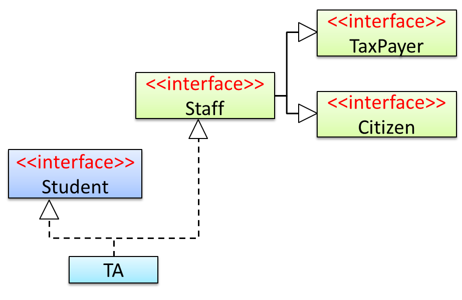
Staffinterface inherits (note the solid lines) the interfacesTaxPayerandCitizen.TAclass implements bothStudentinterface and theStaffinterface.- Because of point 1 above,
TAclass has to implement all methods in the interfacesTaxPayerandCitizen. - Because of points 1,2,3, a
TAis aStaff, is aTaxPayerand is aCitizen.
Interfaces can also contain constants and static methods.
This example adds a constant MAX_SPEED and a static method isSpeedAllowed to the interface DrivableVehicle.
public interface DrivableVehicle {
int MAX_SPEED = 150;
static boolean isSpeedAllowed(int speed){
return speed <= MAX_SPEED;
}
void turn(Direction direction);
void changeLanes(Direction direction);
void signalTurn(Direction direction, boolean signalOn);
// more method signatures
}
Interfaces can contain default method implementations and nested types. They are not covered here.
Java is a strongly-typed language which means the code works with only the object types that it targets.
The following code PetShelter keeps a list of Cat objects and make them speak. The code will not work with any other type, for example, Dog objects.
public class PetShelter {
private static Cat[] cats = new Cat[]{
new Cat("Mittens"),
new Cat("Snowball")};
public static void main(String[] args) {
for (Cat c: cats){
System.out.println(c.speak());
}
}
}
Mittens: Meow
Snowball: Meow
This strong-typing can lead to unnecessary verbosity caused by repetitive similar code that do similar things with different object types.
If the PetShelter is to keep both cats and dogs, you'll need two arrays and two loops:
public class PetShelter {
private static Cat[] cats = new Cat[]{
new Cat("Mittens"),
new Cat("Snowball")};
private static Dog[] dogs = new Dog[]{
new Dog("Spot")};
public static void main(String[] args) {
for (Cat c: cats){
System.out.println(c.speak());
}
for(Dog d: dogs){
System.out.println(d.speak());
}
}
}
Mittens: Meow
Snowball: Meow
Spot: Woof
A better way is to take advantage of polymorphism to write code that targets a superclass so that it works with any subclass objects.
The PetShelter2 uses one data structure to keep both types of animals and one loop to make them speak. The code targets the Animal superclass (assuming Cat and Dog inherits from the Animal class) instead of repeating the code for each animal type.
public class PetShelter2 {
private static Animal[] animals = new Animal[]{
new Cat("Mittens"),
new Cat("Snowball"),
new Dog("Spot")};
public static void main(String[] args) {
for (Animal a: animals){
System.out.println(a.speak());
}
}
}
Mittens: Meow
Snowball: Meow
Spot: Woof
Explanation: Because Java supports polymorphism, you can store both Cat and Dog objects in an array of Animal objects. Similarly, you can call the speak method on any Animal object (as done in the loop) and yet get different behavior from Cat objects and Dog objects.
Suggestion: try to add an Animal object (e.g., new Animal("Unnamed")) to the animals array and see what happens.
Polymorphic code is better in several ways:
- It is shorter.
- It is simpler.
- It is more flexible (in the above example, the
mainmethod will work even if we add more animal types).
In Java, an abstract method is declared with the keyword abstract and given without an implementation. If a class includes abstract methods, then the class itself must be declared abstract.
The speak method in this Animal class is abstract. Note how the method signature ends with a semicolon and there is no method body. This makes sense as the implementation of the speak method depends on the type of the animal and it is meaningless to provide a common implementation for all animal types.
public abstract class Animal {
protected String name;
public Animal(String name){
this.name = name;
}
public abstract String speak();
}
As one method of the class is abstract, the class itself is abstract.
An abstract class is declared with the keyword abstract. Abstract classes can be used as reference type but cannot be instantiated.
This Account class has been declared as abstract although it does not have any abstract methods. Attempting to instantiate Account objects will result in a compile error.
public abstract class Account {
int number;
void close(){
//...
}
}
Account a; OK to use as a type
a = new Account(); Compile error!
In Java, even a class that does not have any abstract methods can be declared as an abstract class.
When an abstract class is subclassed, the subclass should provide implementations for all of the abstract methods in its superclass or else the subclass must also be declared abstract.
The Feline class below inherits from the abstract class Animal but it does not provide an implementation for the abstract method speak. As a result, the Feline class needs to be abstract too.
public abstract class Feline extends Animal {
public Feline(String name) {
super(name);
}
}
The DomesticCat class inherits the abstract Feline class and provides the implementation for the abstract method speak. As a result, it need not be (but can be) declared as abstract.
public class DomesticCat extends Feline {
public DomesticCat(String name) {
super(name);
}
@Override
public String speak() {
return "Meow";
}
}
Animal a = new Feline("Mittens");
Compile error!Felineis abstract.Animal a = new DomesticCat("Mittens");
OK.DomesticCatcan be instantiated and assigned to a variable ofAnimaltype (the assignment is allowed by polymorphism).
Exceptions
Given below is an extract from the -- Java Tutorial, with some adaptations.
There are three basic categories of exceptions In Java:
- Checked exceptions: exceptional conditions that a well-written application should anticipate and recover from. All exceptions are checked exceptions, except for
Error,RuntimeException, and their subclasses.
Suppose an application prompts a user for an input file name, then opens the file by passing the name to the constructor for java.io.FileReader. Normally, the user provides the name of an existing, readable file, so the construction of the FileReader object succeeds, and the execution of the application proceeds normally. But sometimes the user supplies the name of a nonexistent file, and the constructor throws java.io.FileNotFoundException. A well-written program will catch this exception and notify the user of the mistake, possibly prompting for a corrected file name.
- Errors: exceptional conditions that are external to the application, and that the application usually cannot anticipate or recover from. Errors are those exceptions indicated by
Errorand its subclasses.
Suppose that an application successfully opens a file for input, but is unable to read the file because of a hardware or system malfunction. The unsuccessful read will throw java.io.IOError. An application might choose to catch this exception, in order to notify the user of the problem — but it also might make sense for the program to print a stack trace and exit.
- Runtime exceptions: conditions that are internal to the application, and that the application usually cannot anticipate or recover from. Runtime exceptions are those indicated by
RuntimeExceptionand its subclasses. These usually indicate programming bugs, such as logic errors or improper use of an API.
Consider the application described previously that passes a file name to the constructor for FileReader. If a logic error causes a null to be passed to the constructor, the constructor will throw NullPointerException. The application can catch this exception, but it probably makes more sense to eliminate the bug that caused the exception to occur.
Errors and runtime exceptions are collectively known as unchecked exceptions.
A program can catch exceptions by using a combination of the try, catch blocks.
- The
tryblock identifies a block of code in which an exception can occur. - The
catchblock identifies a block of code, known as an exception handler, that can handle a particular type of exception.
The writeList() method below calls a method process() that can cause two type of exceptions. It uses a try-catch construct to deal with each exception.
public void writeList() {
print("starting method");
try {
print("starting process");
process();
print("finishing process");
} catch (IndexOutOfBoundsException e) {
print("caught IOOBE");
} catch (IOException e) {
print("caught IOE");
}
print("finishing method");
}
Some possible outputs:
| No exceptions | IOException | IndexOutOfBoundsException |
|---|---|---|
| starting method starting process finishing process finishing method | starting method starting process caught IOE finishing method | starting method starting process caught IOOBE finishing method |
You can use a finally block to specify code that is guaranteed to execute with or without the exception. This is the right place to close files, recover resources, and otherwise clean up after the code enclosed in the try block.
The writeList() method below has a finally block:
public void writeList() {
print("starting method");
try {
print("starting process");
process();
print("finishing process");
} catch (IndexOutOfBoundsException e) {
print("caught IOOBE");
} catch (IOException e) {
print("caught IOE");
} finally {
// clean up
print("cleaning up");
}
print("finishing method");
}
Some possible outputs:
| No exceptions | IOException | IndexOutOfBoundsException |
|---|---|---|
| starting method starting process finishing process cleaning up finishing method | starting method starting process caught IOE cleaning up finishing method | starting method starting process caught IOOBE cleaning up finishing method |
The
trystatement should contain at least onecatchblock or a finally block and may have multiplecatchblocks.The class of the exception object indicates the type of exception thrown. The exception object can contain further information about the error, including an error message.
You can use the throw statement to throw an exception. The throw statement requires a object as the argument.
Here's an example of a throw statement.
if (size == 0) {
throw new EmptyStackException();
}
In Java, Checked exceptions are subject to the Catch or Specify Requirement: code that might throw checked exceptions must be enclosed by either of the following:
- A
trystatement that catches the exception. Thetrymust provide a handler for the exception. - A method that specifies that it can throw the exception. The method must provide a
throwsclause that lists the exception.
Unchecked exceptions are not required to follow to the Catch or Specify Requirement but you can apply the requirement to them too.
Here's an example of a method specifying that it throws certain checked exceptions:
public void writeList() throws IOException, IndexOutOfBoundsException {
print("starting method");
process();
print("finishing method");
}
Some possible outputs:
| No exceptions | IOException | IndexOutOfBoundsException |
|---|---|---|
| starting method finishing method | starting method | starting method |
Java comes with a collection of built-in exception classes that you can use. When they are not enough, it is possible to create your own exception classes.
Generics
Given below is an extract from the -- Java Tutorial, with some adaptations.
You can use polymorphism to write code that can work with multiple types, but that approach has some shortcomings.
Consider the following Box class. It can be used only for storing Integer objects.
public class BoxForIntegers {
private Integer x;
public void set(Integer x) {
this.x = x;
}
public Integer get() {
return x;
}
}
To store String objects, another similar class is needed, resulting in the duplication of the entire class. As you can see, if you need to store many different types of objects, you could end up writing many similar classes.
public class BoxForString {
private String x;
public void set(String x) {
this.x = x;
}
public String get() {
return x;
}
}
One solution for this problem is to use polymorphism i.e., write the Box class to store Object objects.
public class Box {
private Object x;
public void set(Object x) {
this.x = x;
}
public Object get() {
return x;
}
}
The problem with this solution is, since its methods accept or return an Object, you are free to pass in whatever you want, provided that it is not one of the primitive types. There is no way to verify, at compile time, how the class is used. One part of the code may place an Integer in the box and expect to get Integers out of it, while another part of the code may mistakenly pass in a String, resulting in a runtime error.
Generics enable types (classes and interfaces) to be parameters when defining classes, interfaces and methods. Much like the more familiar , type parameters provide a way for you to re-use the same code with different inputs. The difference is that the inputs to formal parameters are values, while the inputs to type parameters are types.
A generic Box class allows you to define what type of elements will be put in the Box. For example, you can instantiate a Box object to keep Integer elements so that any attempt to put a non-Integer object in that Box object will result in a compile error.
This section includes extract from the -- Java Tutorial, with some adaptations.
The definition of a generic class includes a type parameter section, delimited by angle brackets (<>). It specifies the type parameters (also called type variables) T1, T2, ..., and Tn. A generic class is defined with the following format:
class name<T1, T2, ..., Tn> { /* ... */ }
Here is a generic Box class. The class declaration Box<T> introduces the type variable, T, which is also used inside the class to refer to the same type.
Using Object as the type:
public class Box {
private Object x;
public void set(Object x) {
this.x = x;
}
public Object get() {
return x;
}
}
A generic Box using type parameter T:
public class Box<T> {
private T x;
public void set(T x) {
this.x = x;
}
public T get() {
return x;
}
}
As you can see, all occurrences of Object are replaced by T.
To reference the generic Box class from within your code, you must perform a generic type invocation, which replaces T with some concrete value, such as Integer. It is similar to an ordinary method invocation, but instead of passing an argument to a method, you are passing a type argument enclosed within angle brackets — e.g., <Integer> or <String, Integer> — to the generic class itself. Note that in some cases you can omit the type parameter i.e., <> if the type parameter can be inferred from the context.
Using the generic Box class to store Integer objects:
Box<Integer> integerBox;
integerBox = new Box<>(); // type parameter omitted as it can be inferred
integerBox.set(Integer.valueOf(4));
Integer i = integerBox.get(); // returns an Integer
Box<Integer> integerBox;simply declares thatintegerBoxwill hold a reference to a "Box of Integer", which is howBox<Integer>is read.integerBox = new Box<>();instantiates aBox<Integer>class. Note the<>(an empty pair of angle brackets, also called the diamond operator) between the class name and the parenthesis.
The compiler is able to check for type errors when using generic code.
The code below will fail because it creates a Box<String> and then tries to pass Double objects into it.
Box<String> stringBox = new Box<>();
stringBox.set(Double.valueOf(5.0)); //compile error!
A generic class can have multiple type parameters.
The generic OrderedPair class, which implements the generic Pair interface:
public interface Pair<K, V> {
public K getKey();
public V getValue();
}
public class OrderedPair<K, V> implements Pair<K, V> {
private K key;
private V value;
public OrderedPair(K key, V value) {
this.key = key;
this.value = value;
}
public K getKey() { return key; }
public V getValue() { return value; }
}
The following statements create two instantiations of the OrderedPair class:
Pair<String, Integer> p1 = new OrderedPair<>("Even", 8);
Pair<String, String> p2 = new OrderedPair<>("hello", "world");
The code, new OrderedPair<String, Integer>, instantiates K as a String and V as an Integer. Therefore, the parameter types of OrderedPair's constructor are String and Integer, respectively.
A type variable can be any non-primitive type you specify: any class type, any interface type, any array type, or even another type variable.
By convention, type parameter names are single, uppercase letters. The most commonly used type parameter names are:
E- Element (used extensively by the Java Collections Framework)K- KeyN- NumberT- TypeV- ValueS,U,Vetc. - 2nd, 3rd, 4th types
Collections
This section uses extracts from the -- Java Tutorial, with some adaptations.
A collection — sometimes called a container — is simply an object that groups multiple elements into a single unit. Collections are used to store, retrieve, manipulate, and communicate aggregate data.
Typically, collections represent data items that form a natural group, such as a poker hand (a collection of cards), a mail folder (a collection of letters), or a telephone directory (a mapping of names to phone numbers).
The collections framework is a unified architecture for representing and manipulating collections. It contains the following:
Interfaces: These are abstract data types that represent collections. Interfaces allow collections to be manipulated independently of the details of their representation.
Example: theList<E>interface can be used to manipulate list-like collections which may be implemented in different ways such asArrayList<E>orLinkedList<E>.Implementations: These are the concrete implementations of the collection interfaces. In essence, they are reusable data structures.
Example: theArrayList<E>class implements theList<E>interface while theHashMap<K, V>class implements theMap<K, V>interface.Algorithms: These are the methods that perform useful computations, such as searching and sorting, on objects that implement collection interfaces. The algorithms are said to be polymorphic: that is, the same method can be used on many different implementations of the appropriate collection interface.
Example: thesort(List<E>)method can sort a collection that implements theList<E>interface.
A well-known example of collections frameworks is the C++ Standard Template Library (STL). Although both are collections frameworks and the syntax look similar, note that there are important philosophical and implementation differences between the two.
The following list describes the core collection interfaces:
Collection— the root of the collection hierarchy. A collection represents a group of objects known as its elements. The Collection interface is the least common denominator that all collections implement and is used to pass collections around and to manipulate them when maximum generality is desired. Some types of collections allow duplicate elements, and others do not. Some are ordered and others are unordered. The Java platform doesn't provide any direct implementations of this interface but provides implementations of more specific subinterfaces, such asSetandList. Also see theCollectionAPI.Set— a collection that cannot contain duplicate elements. This interface models the mathematical set abstraction and is used to represent sets, such as the cards comprising a poker hand, the courses making up a student's schedule, or the processes running on a machine. Also see theSetAPI.List— an ordered collection (sometimes called a sequence).Lists can contain duplicate elements. The user of aListgenerally has precise control over where in the list each element is inserted and can access elements by their integer index (position). Also see theListAPI.Queue— a collection used to hold multiple elements prior to processing. Besides basicCollectionoperations, aQueueprovides additional insertion, extraction, and inspection operations. Also see theQueueAPI.Map— an object that maps keys to values. AMapcannot contain duplicate keys; each key can map to at most one value. Also see theMapAPI.Others:
Deque,SortedSet,SortedMap
The ArrayList class is a resizable-array implementation of the List interface. Unlike a normal array, an ArrayList can grow in size as you add more items to it. The example below illustrates some of the useful methods of the ArrayList class using an ArrayList of String objects.
import java.util.ArrayList;
public class ArrayListDemo {
public static void main(String args[]) {
ArrayList<String> items = new ArrayList<>();
System.out.println("Before adding any items:" + items);
items.add("Apple");
items.add("Box");
items.add("Cup");
items.add("Dart");
print("After adding four items: " + items);
items.remove("Box"); // remove item "Box"
print("After removing Box: " + items);
items.add(1, "Banana"); // add "Banana" at index 1
print("After adding Banana: " + items);
items.add("Egg"); // add "Egg", will be added to the end
items.add("Cup"); // add another "Cup"
print("After adding Egg: " + items);
print("Number of items: " + items.size());
print("Index of Cup: " + items.indexOf("Cup"));
print("Index of Zebra: " + items.indexOf("Zebra"));
print("Item at index 3 is: " + items.get(2));
print("Do we have a Box?: " + items.contains("Box"));
print("Do we have an Apple?: " + items.contains("Apple"));
items.clear();
print("After clearing: " + items);
}
private static void print(String text) {
System.out.println(text);
}
}
Before adding any items:[]
After adding four items: [Apple, Box, Cup, Dart]
After removing Box: [Apple, Cup, Dart]
After adding Banana: [Apple, Banana, Cup, Dart]
After adding Egg: [Apple, Banana, Cup, Dart, Egg, Cup]
Number of items: 6
Index of Cup: 2
Index of Zebra: -1
Item at index 3 is: Cup
Do we have a Box?: false
Do we have an Apple?: true
After clearing: []
HashMap is an implementation of the Map interface. It allows you to store a collection of key-value pairs. The example below illustrates how to use a HashMap<String, Point> to maintain a list of coordinates and their identifiers e.g., the identifier x1 is used to identify the point 0,0 where x1 is the key and 0,0 is the value.
import java.awt.Point;
import java.util.HashMap;
import java.util.Map;
public class HashMapDemo {
public static void main(String[] args) {
HashMap<String, Point> points = new HashMap<>();
// put the key-value pairs in the HashMap
points.put("x1", new Point(0, 0));
points.put("x2", new Point(0, 5));
points.put("x3", new Point(5, 5));
points.put("x4", new Point(5, 0));
// retrieve a value for a key using the get method
print("Coordinates of x1: " + pointAsString(points.get("x1")));
// check if a key or a value exists
print("Key x1 exists? " + points.containsKey("x1"));
print("Key y1 exists? " + points.containsKey("y1"));
print("Value (0,0) exists? " + points.containsValue(new Point(0, 0)));
print("Value (1,2) exists? " + points.containsValue(new Point(1, 2)));
// update the value of a key to a new value
points.put("x1", new Point(-1,-1));
// iterate over the entries
for (Map.Entry<String, Point> entry : points.entrySet()) {
print(entry.getKey() + " = " + pointAsString(entry.getValue()));
}
print("Number of keys: " + points.size());
points.clear();
print("Number of keys after clearing: " + points.size());
}
public static String pointAsString(Point p) {
return "[" + p.x + "," + p.y + "]";
}
public static void print(String s) {
System.out.println(s);
}
}
Coordinates of x1: [0,0]
Key x1 exists? true
Key y1 exists? false
Value (0,0) exists? true
Value (1,2) exists? false
x1 = [-1,-1]
x2 = [0,5]
x3 = [5,5]
x4 = [5,0]
Number of keys: 4
Number of keys after clearing: 0
[END OF BOOK]