Unified Modeling Language (UML) is a graphical notation to describe various aspects of a software system. UML is the brainchild of three software modeling specialists James Rumbaugh, Grady Booch and Ivar Jacobson (also known as the Three Amigos). Each of them had developed their own notation for modeling software systems before joining forces to create a unified modeling language (hence, the term ‘Unified’ in UML). UML is currently the most commonly used modeling notation used in the software industry.
The following diagram uses the class diagram notation to show the different types of UML diagrams.

source:https://en.wikipedia.org/
An OO solution is basically a network of objects interacting with each other. Therefore, it is useful to be able to model how the relevant objects are 'networked' together inside a software i.e., how the objects are connected together.
Given below is an illustration of some objects and how they are connected together. Note: the diagram uses an ad-hoc notation.
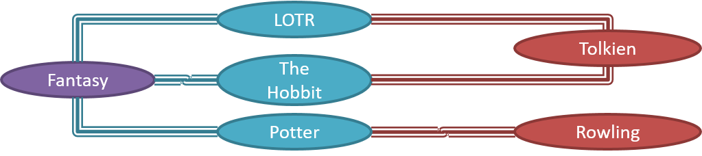
Note that these object structures within the same software can change over time.
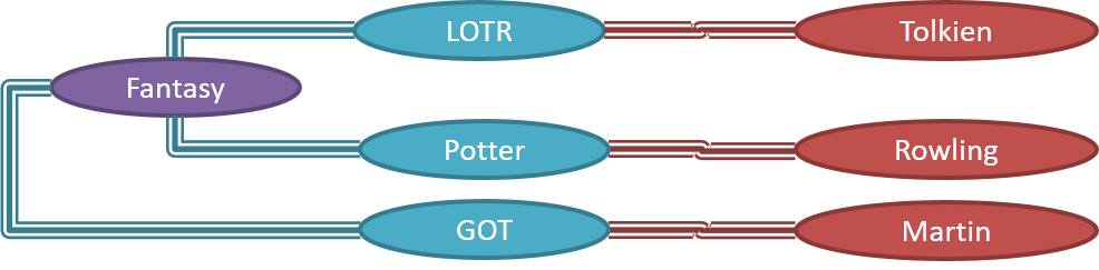
Given below is how the object structure in the previous example could have looked like at a different time.
However, object structures do not change at random; they change based on a set of rules set by the designer of that software. Those rules that object structures need to follow can be illustrated as a class structure i.e., a structure that exists among the relevant classes.
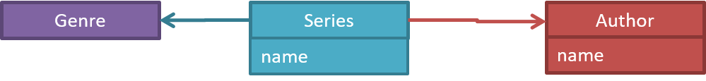
Here is a class structure (drawn using an ad-hoc notation) that matches the object structures given in the previous two examples. For example, note how this class structure does not allow any connection between Genre objects and Author objects, a rule followed by the two object structures above.

UML Object Diagrams model object structures. UML Class Diagrams model class structures.
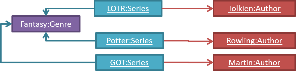
Here is an object diagram for the above example:
And here is the class diagram for it:
Classes form the basis of class diagrams.
Associations are the main connections among the classes in a class diagram.
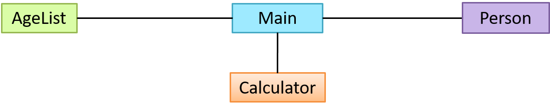
The most basic class diagram is a bunch of classes with some solid lines among them to represent associations, such as this one.
An example class diagram showing associations between classes.
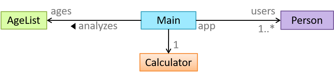
In addition, associations can show additional decorations such as association labels, association roles, multiplicity and navigability to add more information to a class diagram.
Here is the same class diagram shown earlier but with some additional information included:
The analysis process for identifying objects and object classes is recognized as one of the most difficult areas of object-oriented development. --Ian Sommerville, in the book Software Engineering
Sidebar: Domain Modeling
Domain modeling is modeling the i.e., to model how things actually work in the real world. Domain modeling is useful in understanding the problem domain, which is essential to the success of a project.
Domain modeling can be done using,
- a domain-specific modeling notation if such a notation exists (e.g., a modeling notation specific to the banking domain might have elements to represent loans, accounts, transactions etc.),
- or a general purpose modeling notation, such as UML (e.g., you can use an activity diagram to model the workflow of processing a loan application),
- or even other general purpose notations (e.g., you can use an organization chart to model the employee hierarchy of a company).
When building an OOP system, it makes sense to build OOP models of the problem domain, given OOP aspires to emulate the objects in the real world.
The UML model that captures class structures in the problem domain are called conceptual class diagrams. They are in fact a lighter version of class diagrams, and sometimes also called OO domain models (OODMs). The latter name is somewhat misleading as conceptual class diagrams (CCDs) are actually only one type of domain models that can model an OOP problem domain.
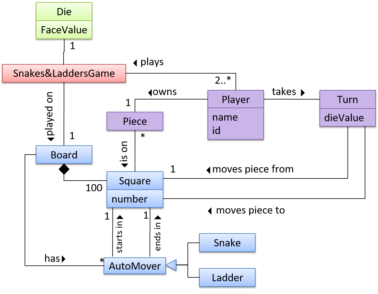
The CCD of a snakes and ladders game is given below.
Description: The snakes and ladders game is played by two or more players using a board and a die. The board has 100 squares marked 1 to 100. Each player owns one piece. Players take turns to throw the die and advance their piece by the number of squares they earned from the die throw. The board has a number of snakes. If a player’s piece lands on a square with a snake head, the piece is automatically moved to the square containing the snake’s tail. Similarly, a piece can automatically move from a ladder foot to the ladder top. The player whose piece is the first to reach the 100th square wins.
CCDs do not contain solution-specific classes (i.e., classes that are used in the solution domain but do not exist in the problem domain). For example, a class called DatabaseConnection could appear in a class diagram but not usually in a CCD because DatabaseConnection is something related to a software solution but not an entity in the problem domain.
CCDs represents the class structure of the problem domain and not their behavior, just like class diagrams. To show behavior, use other diagrams such as sequence diagrams.
CCD notation is a subset of the class diagram notation (omits methods and navigability).
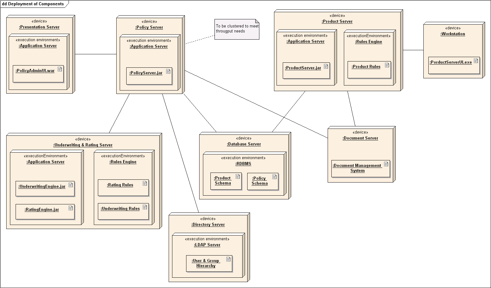
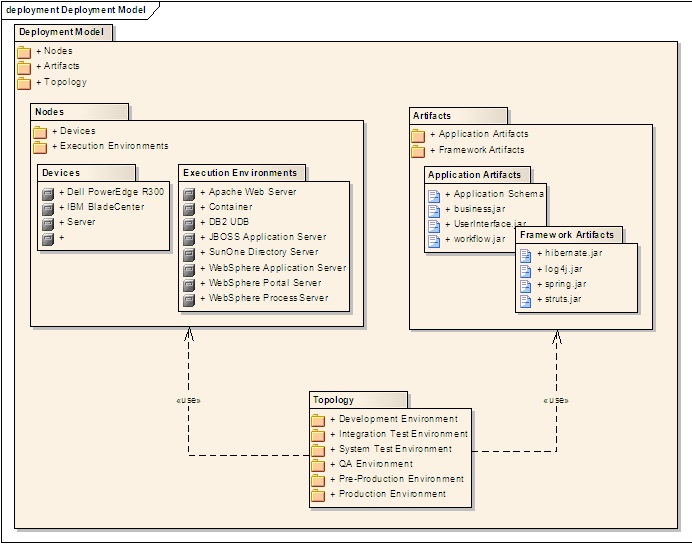
A deployment diagram shows a system's physical layout, revealing which pieces of software run on which pieces of hardware.
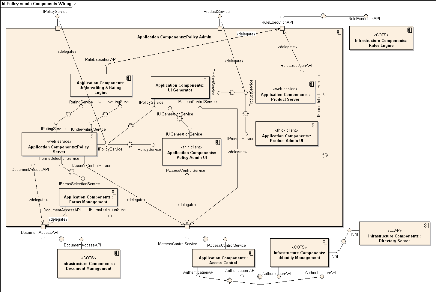
A component diagram is used to show how a system is divided into components and how they are connected to each other through interfaces.
A package diagram shows packages and their dependencies. A package is a grouping construct for grouping UML elements (classes, use cases, etc.).
Here is an example package diagram:
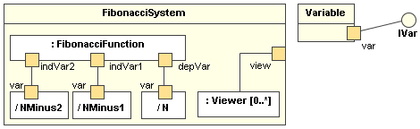
A composite structure diagram hierarchically decomposes a class into its internal structure.
Interaction overview diagrams are a combination of activity diagrams and sequence diagrams.
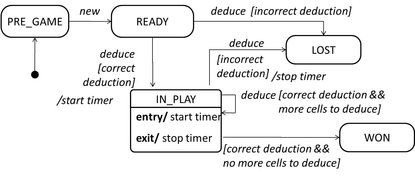
A State Machine Diagram models state-dependent behavior.
Consider how a CD player responds when the “eject CD” button is pushed:
- If the CD tray is already open, it does nothing.
- If the CD tray is already in the process of opening (opened half-way), it continues to open the CD tray.
- If the CD tray is closed and the CD is being played, it stops playing and opens the CD tray.
- If the CD tray is closed and CD is not being played, it simply opens the CD tray.
- If the CD tray is already in the process of closing (closed half-way), it waits until the CD tray is fully closed and opens it immediately afterwards.
What this means is that the CD player’s response to pushing the “eject CD” button depends on what it was doing at the time of the event. More generally, the CD player’s response to the event received depends on its internal state. Such a behavior is called a state-dependent behavior.
Often, state-dependent behavior displayed by an object in a system is simple enough that it needs no extra attention; such a behavior can be as simple as a conditional behavior like if x > y, then x = x - y.
Occasionally, objects may exhibit state-dependent behavior that is complex enough such that it needs to be captured in a separate model. Such state-dependent behavior can be modeled using UML state machine diagrams (SMD for short, sometimes also called ‘state charts’, ‘state diagrams’ or ‘state machines’).
An SMD views the life-cycle of an object as consisting of a finite number of states where each state displays a unique behavior pattern. SMDs capture information such as the states an object can be in during its lifetime, how the object responds to various events while in each state, and how the object transits from one state to another. In contrast to sequence diagrams that capture object behavior one scenario at a time, SMDs capture the object’s behavior over its full life-cycle.
An SMD for the Minesweeper game.
You can use models to analyze and design software before you start coding.
Suppose you are planning to implement a simple minesweeper game that has a text based UI and a GUI. Given below is a possible OOP design for the game.

Before jumping into coding, you may want to find out things such as,
- Is this class structure able to produce the behavior you want?
- What API should each class have?
- Do you need more classes?
To answer these questions, you can analyze how the objects of these classes will interact with each other to produce the behavior you want.
As mentioned in [Design → Modeling → Modeling a Solution → Introduction], this is the Minesweeper design you have come up with so far. Our objective is to analyze, evaluate, and refine that design.
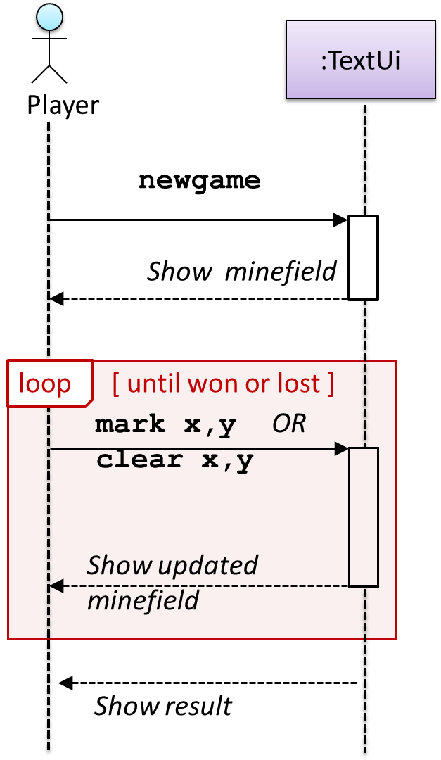
Let us start by modeling a sample interaction between the person playing the game and the TextUi object.
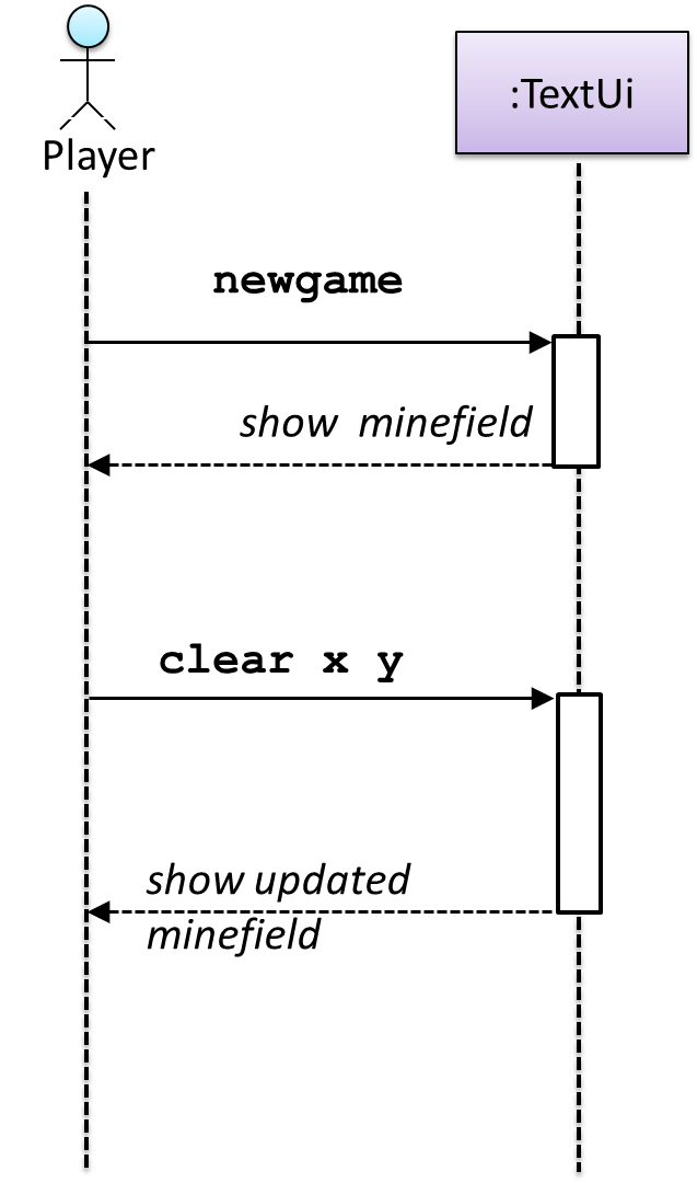
newgame and clear x y represent commands typed by the Player on the TextUi.
How does the TextUi object carry out the requests it has received from the player? It would need to interact with other objects of the system. Because the Logic class is the one that controls the game logic, the TextUi needs to collaborate with Logic to fulfill the newgame request. Let us extend the model to capture that interaction.
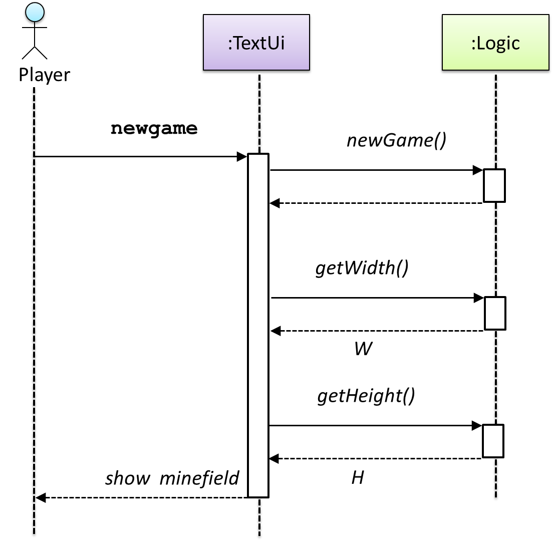
W = Width of the minefield; H = Height of the minefield
The above diagram assumes that W and H are the only information TextUi requires to display the minefield to the Player. Note that there could be other ways of doing this.
The Logic methods you conceptualized in our modeling so far are:
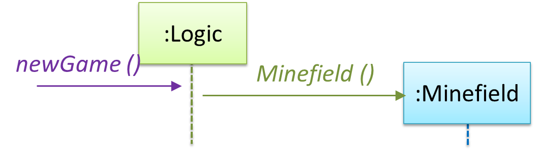
Now, let us look at what other objects and interactions are needed to support the newGame() operation. It is likely that a new Minefield object is created when the newGame() method is called.
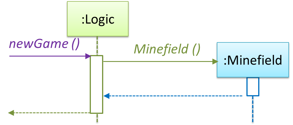
Note that the behavior of the Minefield constructor has been abstracted away. It can be designed at a later stage.
Given below are the interactions between the player and the TextUi for the whole game.
Note that can be used when discovering/defining the architecture-level APIs.
Defining the architecture-level APIs for a small Tic-Tac-Toe game:
Continuing with the example in [Design → Modeling → Modeling a Solution → Basic], next let us model how the TextUi interacts with the Logic to support the mark and clear operations until the game is won or lost.
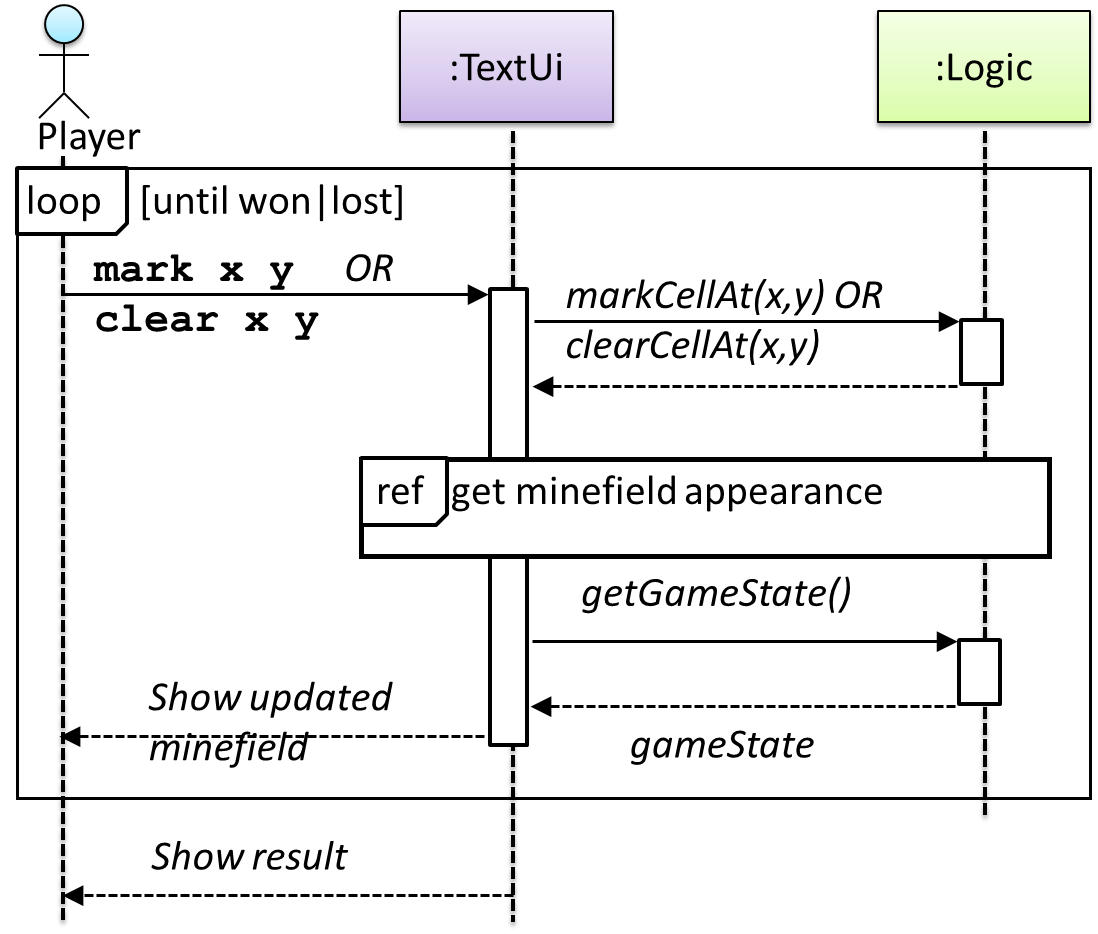
This interaction adds the following methods to the Logic class:
clearCellAt(int x, int y)markCellAt(int x, int y)getGameState(): GAME_STATE (GAME_STATE: READY, IN_PLAY, WON, LOST, …)
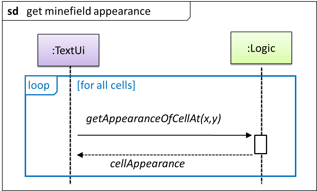
And it adds the following operation to Logic API:
getAppearanceOfCellAt(int,int): CELL_APPEARANCE (CELL_APPEARANCE: HIDDEN, ZERO, ONE, TWO, THREE, …, MARKED, INCORRECTLY_MARKED, INCORRECTLY_CLEARED)
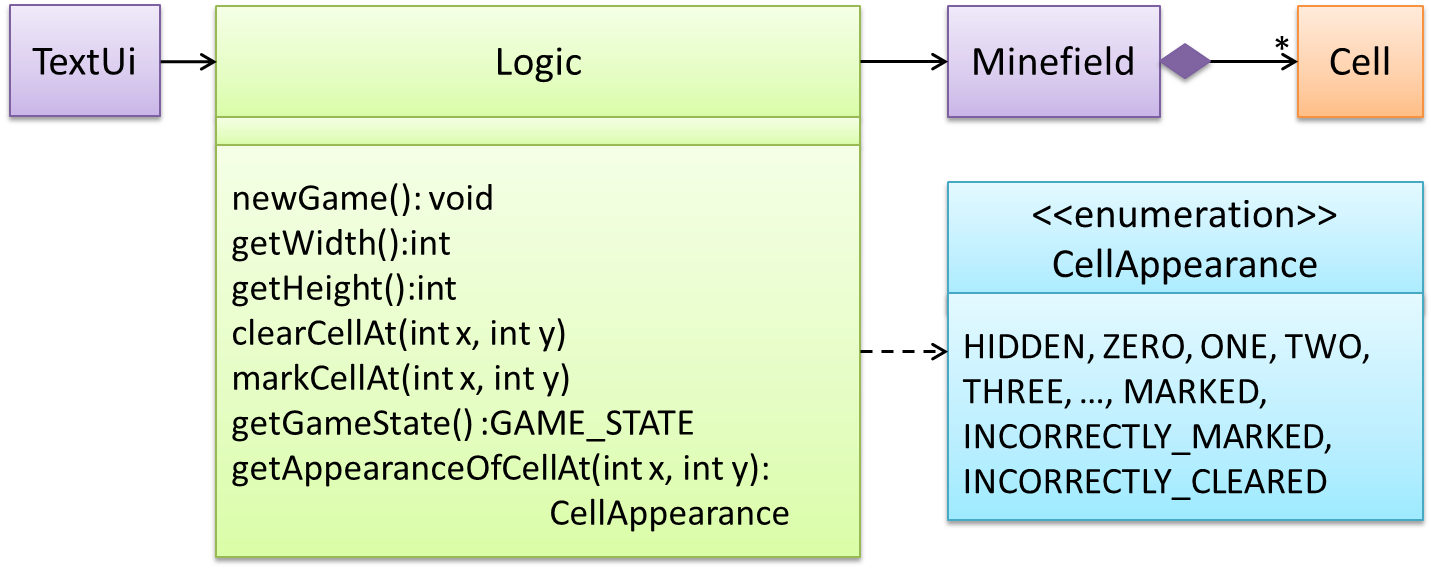
In the above design, TextUi does not access Cell objects directly. Instead, it gets values of type CELL_APPEARANCE from Logic to be displayed as a minefield to the player. Alternatively, each cell or the entire minefield can be passed directly to TextUi.
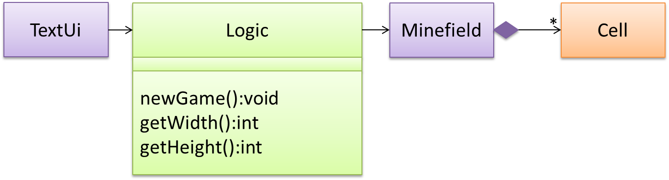
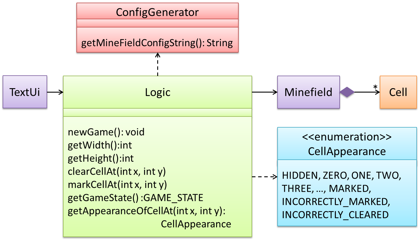
Here is the updated class diagram:
The above is for the case when Actor Player interacts with the system using a text UI. Additional operations (if any) required for the GUI can be discovered similarly.
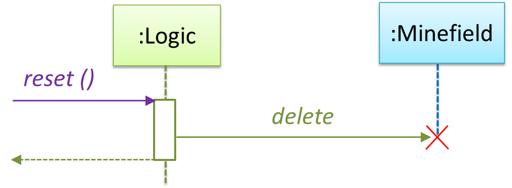
Suppose Logic supports a reset() operation. You can model it like this:
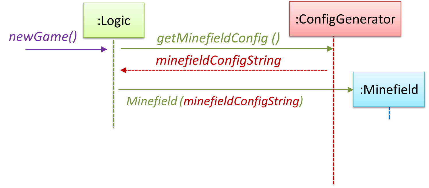
Our current model assumes that the Minefield object has enough information (i.e., H, W, and mine locations) to create itself.
An alternative is to have a ConfigGenerator object that generates a string containing the minefield information as shown below.
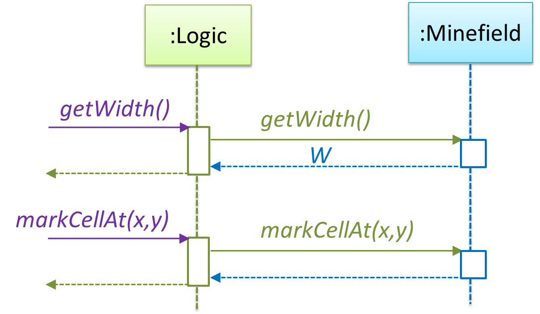
In addition, getWidth(), getHeight(), markCellAt(x,y) and clearCellAt(x,y) can be handled like this.
The updated class diagram:
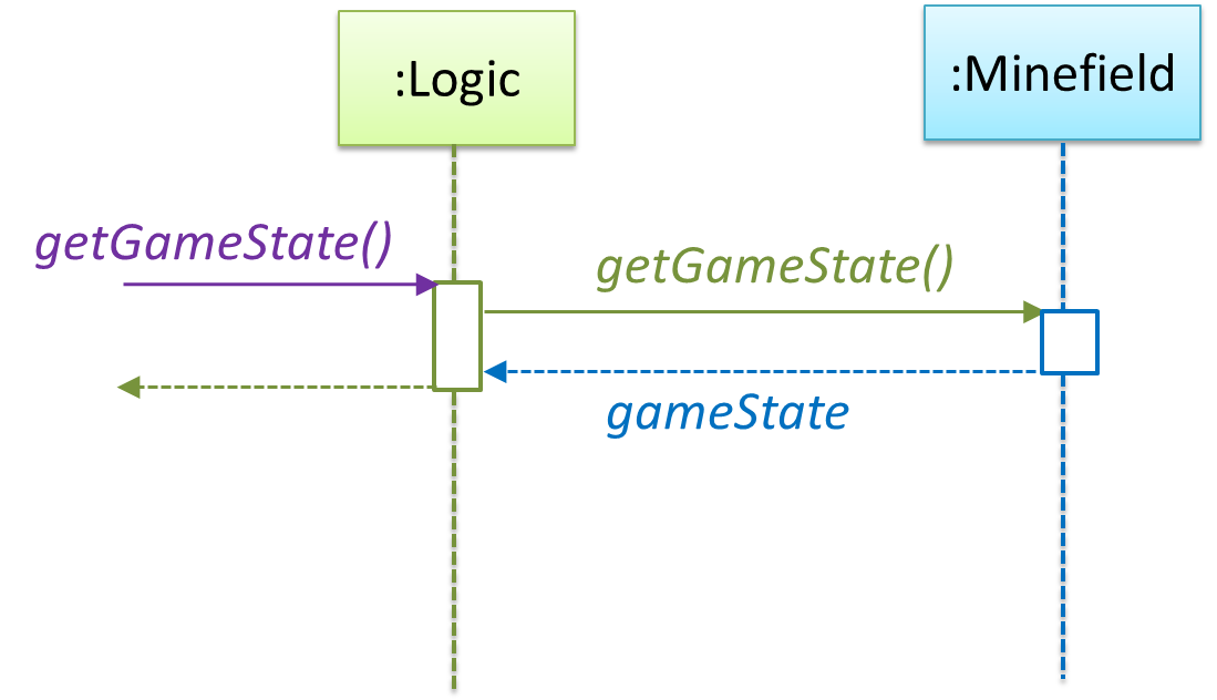
How is the getGameState() operation supported? Given below are two ways (there could be other ways):
- The
Minefieldclass knows the state of the game at any time. TheLogicclass retrieves it from theMinefieldclass as and when required. - The
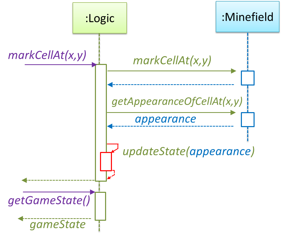
Logicclass maintains the state of the game at all times.
Here’s the SD for option 1.
Here’s the SD for option 2. Assume that the game state is updated after every mark/clear action.
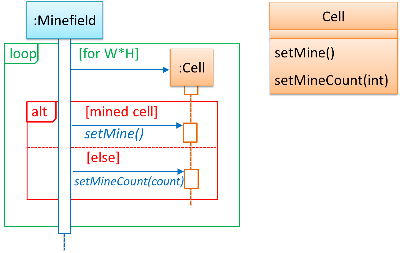
It is now time to explore what happens inside the Minefield constructor. One way is to design it as follows.
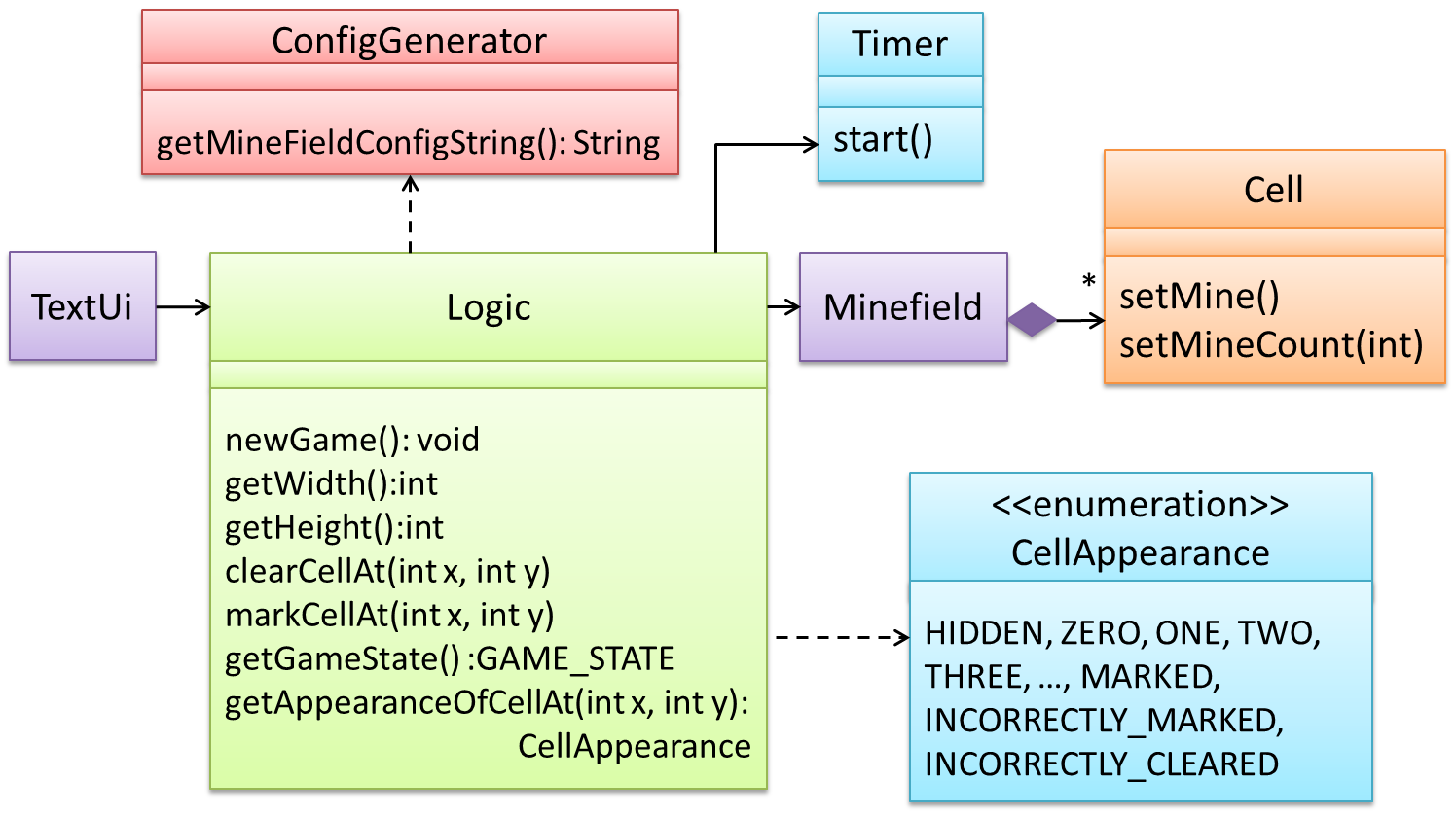
Now let us assume that Minesweeper supports a ‘timing’ feature.
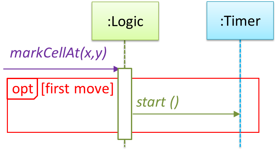
Updated class diagram:
When designing components, it is not necessary to draw elaborate UML diagrams capturing all details of the design. They can be done as rough sketches. For example, draw sequence diagrams only when you are not sure which operations are required by each class, or when you want to verify that your class structure can indeed support the required operations.